Introduction
Imagine pressing the reset button on your development board, akin to launching a rocket. In just a few milliseconds, the STM32 chip undergoes a meticulously orchestrated “booting journey”—waking from slumber, checking its gear, choosing a route, and ultimately arriving at its destination: your main function.
Today, let us embody the CPU inside the chip and personally experience this marvelous journey!
Booting Overview
Application Startup Code Memory BOOT Pin CPU Core Power Application Startup Code Memory BOOT Pin CPU Core Power User Program Starts Running Power Supply POR Reset Initialization Read BOOT Pin Status Return to Boot Mode Read Vector Table (Address 0x00) Return Stack Pointer SP Read Vector Table (Address 0x04) Return Reset Vector PC Jump to Reset_Handler Data Initialization Call SystemInit Configure Clock Jump to Main FunctionFirst Stop: Power-On Reset – Waking from Slumber
The Hardware “Morning Ritual”
Just like you are awakened by an alarm clock in the morning, the “awakening” of the STM32 chip also requires a process. At the moment the power is turned on, the chip does not immediately start working; instead, it undergoes a process called **Power-On Reset (POR)**.
This process is akin to a person waking from deep sleep:
- 1. Opening Eyes: The power voltage gradually rises to the operational threshold (usually around 2.0V).
- 2. Awareness Awakens: The internal reset circuit operates, ensuring all registers return to their initial state.
- 3. Brain Starts: The internal RC oscillator begins to work, providing the basic 8MHz clock signal (HSI).
CPU Core Internal Oscillator POR Circuit Power Voltage CPU Core Internal Oscillator POR Circuit Power Voltage Detect Voltage Stability Initialize Registers to Default Values CPU Ready, Waiting for Execution Voltage Rises to Threshold Release Reset Signal Start Internal Clock Provide 8MHz ClockInitial State Overview
At this point, the STM32 is like a person just waking up, in the most basic operational state:
- • ⏰ Clock: Using the internal 8MHz RC oscillator (HSI).
- • 🧠 CPU State: All registers are zeroed, the program counter PC is waiting for a value.
- • 💾 Memory: Not yet mapped to a specific location.
- • ⚡ Power Consumption: Basic operational mode, waiting for further configuration.
Time Taken for This Stage: Approximately 1-5 milliseconds.
Second Stop: Choosing the Path – BOOT Pin Determines Fate
The Choice at the Fork in the Road
After the reset is released, the CPU faces an important choice: **Where to start executing code?** This is the role of the BOOT pin—it acts like a signpost at the intersection, telling the CPU which path to take.
The STM32 chip has a BOOT0 (and some models also have BOOT1) pin, which can be configured through hardware levels to select from three different “starting points”:
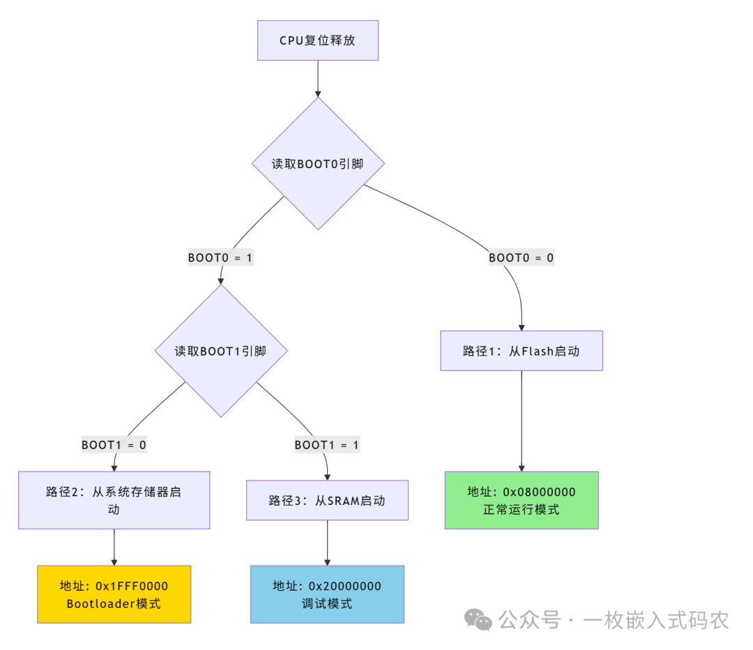
Detailed Explanation of Three Boot Modes
🟢 Path 1: Boot from Flash (Most Common)
| Configuration | Starting Address | Usage | Life Analogy |
|---|---|---|---|
| BOOT0=0 | 0x08000000 | Normal Operation User Program | Booting the Operating System from the Computer Hard Drive |
This is99% of application scenarios, where the program you have burned is stored in Flash, and the chip automatically starts executing from here after power-up.
🟡 Path 2: Boot from System Memory (Bootloader)
| Configuration | Starting Address | Usage | Life Analogy |
|---|---|---|---|
| BOOT0=1, BOOT1=0 | 0x1FFF0000 | ST Official Bootloader | Booting the PE System from a USB Drive |
The system memory contains the ST official pre-installedBootloader program, which supports downloading firmware through interfaces like serial, USB, CAN, etc. This is very useful for on-site upgrades of products—no special programmer is needed!
🔵 Path 3: Boot from SRAM (For Debugging)
| Configuration | Starting Address | Usage | Life Analogy |
|---|---|---|---|
| BOOT0=1, BOOT1=1 | 0x20000000 | Running Program from RAM | Running a Program Directly in Memory |
This mode is used less frequently, mainly for debugging—programs can be loaded directly into RAM via a debugger without needing to burn Flash each time.
Third Stop: Finding the Map – The Secret of the Interrupt Vector Table
The Mysterious “Task List”
Once the CPU has determined the starting point (e.g., 0x08000000), the first thing it needs to do is check theInterrupt Vector Table at that location.
Think of the vector table as a “task list” or “address book” that records various important information. At the very beginning of this “list”, there are two crucial entries:
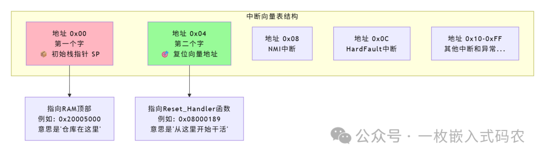
Automatic Operations of the CPU
The CPU hardware willautomatically complete the following two steps (no software code required):
Step 1: Load Stack Pointer
SP = *((uint32_t*)0x00000000); // Read value from address 0x00, load into stack pointer registerThe stack pointer tells the CPU: “Your workspace is at this location in RAM, all temporary data goes here”.
Step 2: Load Program Counter
PC = *((uint32_t*)0x00000004); // Read value from address 0x04, load into program counterThe program counter loads theaddress of the Reset_Handler function, and the CPU will immediately jump here to start executing the first instruction.
Why These Two Values?
Imagine you are about to start your workday:
- • Stack Pointer (SP): Tells you where your desk is (workspace).
- • Reset Vector (PC): Tells you what your first task is (where to start).
With this information, the CPU can happily start working!
Fourth Stop: Preparing to Depart – The Mission of the Startup Code
Reset_Handler: The Unsung Hero
When the CPU jumps to the Reset_Handler function, the real “preparation work” begins. This function is typically defined in thestartup file (startup_stm32xxx.s), and its task is like that of a moving company—putting everything in the right place.
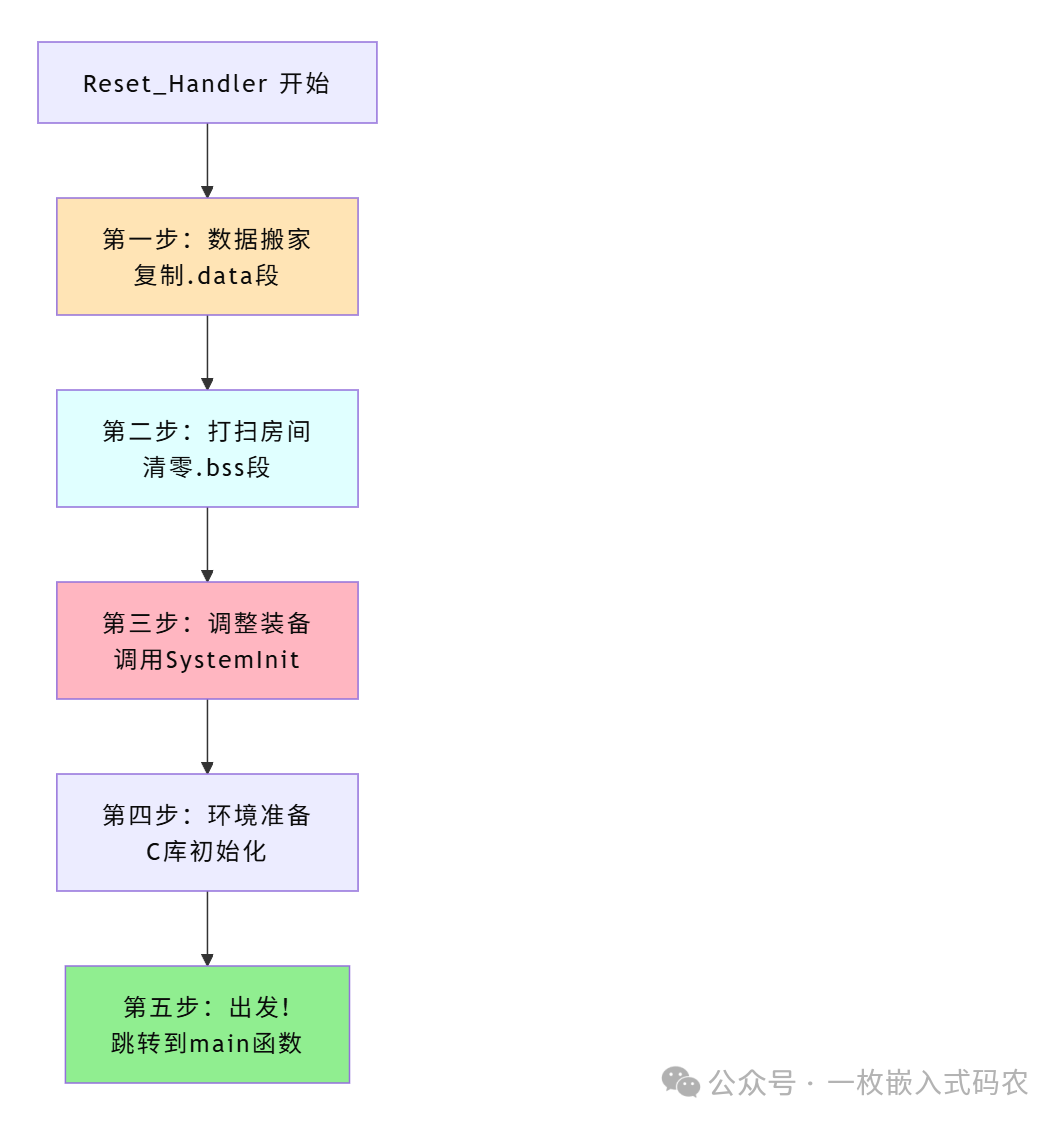
Three Core Tasks Explained
📦 Task 1: Moving Data (Copying .data Segment)
In C language, if you write:
int counter = 100; // Initialized global variableTheinitial value (100) is stored in Flash, but the program needs to read and write it inRAM during execution. Therefore, the first thing the startup code does is:
Copy the initial data from Flash to RAM.
Expressed in pseudocode:
// Move initialized data from Flash to RAM
uint8_t* src = &_sidata;   // Starting point of data in Flash
uint8_t* dst = &_sdata;    // Starting point of data in RAM
while (dst < &_edata) {
    *dst++ = *src++;       // Copy byte by byte
}Analogy: Just like when you move, you take the luggage from the storage cabinet to the rooms in your new home.
🧹 Task 2: Cleaning the Room (Zeroing .bss Segment)
If you write:
int buffer[100]; // Uninitialized global variableThe C language standard stipulates that uninitialized global variables must be automatically zeroed. The startup code is responsible for filling this RAM area with 0:
// Zero out uninitialized variable memory
uint8_t* dst = &_sbss;
while (dst < &_ebss) {
    *dst++ = 0;            // Zero out byte by byte
}Analogy: Just like before moving into a new home, you clean the empty room.
⚙️ Task 3: Adjusting Equipment (Calling SystemInit)
Once the data is prepared, the startup code calls the **SystemInit()** function, which is a user-customizable configuration function mainly used for:
- • Configuring the system clock (to be explained in detail later)
- • Setting Flash access parameters
- • Configuring bus dividers
// Call in startup code
SystemInit();     // System initialization
__main();         // C library initialization, will eventually jump to main
Fifth Stop: Adjusting Equipment – Speeding Up the Clock System
Why Configure the Clock?
Do you remember the internal 8MHz clock mentioned in the first stop? This frequency is too slow for modern applications! It’s like a car still driving in first gear—while it can move, it’s inefficient.
The true performance of the STM32 requires a higher clock frequency:
- • STM32F1 Series: Up to 72MHz
- • STM32F4 Series: Up to 168MHz
- • STM32H7 Series: Up to 480MHz
The “Gear Shift Acceleration” Process of the Clock
The SystemInit function performs a series of clock configurations, switching the system from “first gear” to “high-speed gear”:
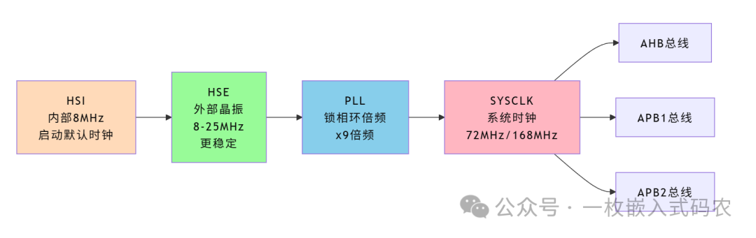
Summary of Configuration Steps
Typical operations of the SystemInit function:
- 1. Enable External Crystal (HSE): Switch to a more stable external clock source.
- 2. Configure PLL Multiplication: For example, 8MHz × 9 = 72MHz.
- 3. Select System Clock Source: Obtain clock from PLL.
- 4. Configure Bus Dividers: Allocate appropriate clock frequencies for different peripherals.
- 5. Set Flash Latency: High-speed operation requires adjusting Flash read timing.
Analogy: Just like a race car driver quickly shifts from first gear to fifth gear after the start, unleashing the full performance of the engine!
Why is Clock Configuration Important?
Clock Frequency
CPU Operation Speed
Peripheral Communication Rate
Power Consumption
Affects Program Execution Efficiency
Affects Data Transmission Speed
Affects Battery Life
Proper clock configuration can find the best balance betweenperformance and power consumption.
Final Stop: Entering the Main Function – The End of the Journey
Once all preparations are complete, the startup code will finally call the familiarmain() function:
int main(void) {
    // 🎉 Congratulations! Your code has finally started executing.
    while(1) {
        // Your application logic
    }
}
From pressing the reset button to entering the main function, the entire process typically takes5-20 milliseconds—in the blink of an eye, the STM32 has completed this wonderful “booting journey”!
Boot Time Breakdown
| Stage | Typical Duration | Main Tasks |
|---|---|---|
| Power-On Reset (POR) | 1-5ms | Power Stabilization, Reset Circuit |
| Reading Vector Table | <1μs | Automatically Completed by Hardware |
| Executing Startup Code | 1-3ms | Data Initialization |
| Clock Configuration | 2-10ms | HSE/PLL Stabilization |
| Total | 5-20ms | Complete Startup Process |
Summary: Review of the Complete Process
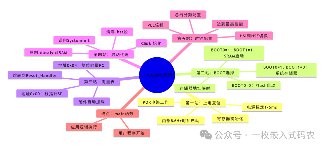
Let us review the complete booting journey of the STM32 with a mind map:
Key Points
✅ Power-On Reset: Automatically completed by hardware, providing the most basic working environment (8MHz clock).
✅ BOOT Pin: Determines where to start; the most common is BOOT0=0 booting from Flash.
✅ Interrupt Vector Table: Located at the starting position of memory, the first two words are the stack pointer and reset vector.
✅ Startup Code: Responsible for moving data (.data) and zeroing (.bss), calling SystemInit.
✅ Clock Configuration: Accelerates from 8MHz to 72MHz/168MHz, unleashing the true performance of the chip.
✅ Entering Main: All preparations complete, user program begins execution.
Final Thoughts
Now you understand the complete process of STM32 booting! Next time you:
- • 🔧 Debug Boot Issues, you will know exactly which part to check.
- • 📝 Read Startup Files, you will understand the purpose of each line of code.
- • ⚡ Optimize Boot Time, you will know where to start.
- • 🎯 Customize Bootloader, you will understand the entire booting mechanism.
Remember, every time you press the reset button, your STM32 completes this marvelous journey in just a few milliseconds—from slumber to awakening, from chaos to order, ultimately handing over control to your code. This is the charm of embedded systems!
Follow us to explore more mysteries of the embedded world together!
This article applies to the entire STM32 series of chips; specific details may vary by model. It is recommended to further study the chip’s “Data Sheet” and “Reference Manual”.
[Previous Recommendations]Advanced Decoupling of Embedded Software Modules: Building High Cohesion, Low Coupling System ArchitectureThe Three Musketeers of Embedded Programming: Practical Uses of Structures, Unions, and Shared DataDecoupling Embedded Software Modules: Three Key Methods from Chaos to Clarity