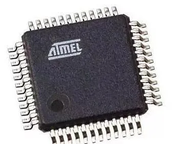
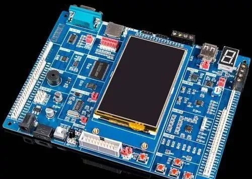
A microcontroller consists of an arithmetic unit, a controller, memory, and input/output devices, and is also known as a single-chip microcontroller. It is not just a chip that performs a specific logical function, but integrates a complete computer system onto a single chip. It is equivalent to a miniature computer, and compared to a computer, a microcontroller only lacks I/O devices. In summary, a single chip can function as a computer. Its small size, light weight, and low cost provide convenient conditions for learning, application, and development. At the same time, learning to use microcontrollers is a great choice for understanding computer principles and structures. Today, let’s explore the important components of microcontroller applications.
1. Bus
We know that a circuit is always formed by connecting components with wires. In analog circuits, wiring is not a problem because the components are generally in a series relationship, and there are not many connections between components. However, computer circuits are different; they are centered around the microprocessor, and all components must be connected to the microprocessor. The operations of all components must coordinate with each other, so many connections are required. If we were to connect each microprocessor and component individually as in an analog circuit, the number of wires would be astonishing. Therefore, the concept of a bus is introduced in microprocessors, where all components share the connections. All eight data lines of the components are connected to eight common lines, which is equivalent to connecting all components in parallel. However, this alone is not sufficient. If two components send data simultaneously, one being 0 and the other being 1, what will the receiver actually receive? This situation is not allowed, so control lines are used to manage the timing of operations, ensuring that only one component can send data at any time (multiple components can receive simultaneously). The data lines of the components are referred to as the data bus, while all control lines are referred to as the control bus. In both internal and external memory and other components of the microcontroller, there are storage units that need to be assigned addresses for use. Address allocation is also given in the form of electrical signals. Since there are many storage units, there are also many lines used for address allocation, which are called address buses.
2. Data, Address, Instruction
The reason for grouping these three together is that their essence is the same—numbers, or sequences composed of ‘0’s and ‘1’s. In other words, addresses and instructions are also data. Instructions: A type of number defined by the designer of the microcontroller chip, which has a strict one-to-one correspondence with the mnemonic instructions we commonly use and cannot be changed by the microcontroller developer. Address: The basis for locating internal and external storage units and input/output ports of the microcontroller. The address values of internal units are predetermined by the chip designer and cannot be changed, while external units can be determined by the microcontroller developer, although some address units must exist (see the execution process of the program for details). Data: This is the object processed by the microprocessor, which varies in different application circuits. Generally speaking, the data being processed may have several situations:
(1) Address (e.g., MOV DPTR, 1000H), which means the address 1000H is sent to DPTR.
(2) Mode word or control word (e.g., MOV TMOD, #3), where 3 is the control word.
(3) Constant (e.g., MOV TH0, #10H), where 10H is the timer constant.
(4) Actual output value (e.g., if port P1 is connected to colored lights, to turn all lights on, execute the instruction: MOV P1, #0FFH; to turn all lights off, execute the instruction: MOV P1, #00H). Here, 0FFH and 00H are both actual output values. For example, the character code used for LEDs is also an actual output value.
3. P0, P2, and P3’s Second Function Usage
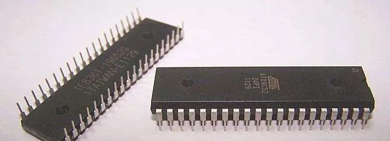
Beginners often find the second function usage of P0, P2, and P3 confusing, thinking that there must be a switching process between the second function and the original function, or that there must be an instruction to switch. In fact, the second function of each port is completely automatic and does not require an instruction to switch. For example, P3.6 and P3.7 are WR and RD signals, respectively. When the microcontroller is connected to RAM or has external I/O ports, they are used as second functions and cannot be used as general I/O ports. As soon as the microcontroller executes the MOVX instruction, the corresponding signal will be sent from P3.6 or P3.7 without needing a prior instruction. In fact, ‘cannot be used as general I/O ports’ does not mean ‘cannot’ but rather that the user ‘will not’ use them as general I/O ports. You can completely arrange an instruction like SETB P3.7 in your code, and when the microcontroller executes this instruction, it will also set P3.7 to high, but users typically do not do this because it usually leads to system crashes.
4. Program Execution Process
After powering on and resetting, the value in the program counter (PC) of the 8051 microcontroller is ‘0000’, so the program always starts executing from the ‘0000’ unit. This means that there must be a ‘0000’ unit in the system’s ROM, and it must contain an instruction.
5. Stack
The stack is an area used to store data. This area itself has no special characteristics; it is just a part of the internal RAM. What is special is the way data is stored and retrieved, known as ‘last in, first out’ (LIFO). The stack has special data transfer instructions, namely ‘PUSH’ and ‘POP’, and a special unit dedicated to it, the stack pointer (SP). Each time a PUSH instruction is executed, SP automatically increments by 1, and each time a POP instruction is executed, SP automatically decrements by 1. Since the value in SP can be changed by instructions, as long as the value of SP is changed at the beginning of the program, the stack can be set in a specified memory unit. For example, at the start of the program, using the instruction MOV SP, #5FH sets the stack to start from memory unit 60H. Generally, there is always an instruction at the beginning of the program to set the stack pointer because at power-on, the initial value of SP is 07H, which causes the stack to start from unit 08H and go forward. The area from 08H to 1FH is the second, third, and fourth working register area of the 8031, which is frequently used, leading to data confusion. Different authors may have different initialization instructions for the stack, which is a matter of personal habit. Once the stack area is set up, it does not mean that this area becomes a dedicated memory; it can still be used like ordinary memory, but generally, programmers do not treat it as ordinary memory.
6. Microcontroller Development Process
The development process mentioned here is not the typical task analysis described in general books. We assume that the hardware has been designed and produced, and the next step is to write the software. Before writing the software, some constants and addresses must be determined. In fact, these constants and addresses have already been directly or indirectly determined during the design phase. For example, once the wiring design of a device is complete, its address is also determined. Once the function of the device is established, its control word is also determined. Then, using a text editor (such as EDIT, CCED, etc.), the software is written. After writing, the source program file is compiled, and errors are checked until there are no syntax errors. Except for very simple programs, a simulator is generally used to debug the software until the program runs correctly. Once it runs correctly, the program can be written to the chip (burned into EPROM). After the source program is compiled, a target file with the extension HEX is generated, which is generally recognized by programmers. The file can be loaded for writing to the chip. To give everyone an understanding of the entire process, here is an example:
ORG 0000H
LJMP START
ORG 040H
START:
MOV SP,#5FH ; Set stack
LOOP:
NOP
LJMP LOOP ; Loop
END ; End
Currently, many people do not recognize assembly language, but mastering C language programming for microcontrollers is very important as it can greatly improve development efficiency. However, beginners may not need to understand assembly language for microcontrollers, but they must understand the specific performance and characteristics of microcontrollers; otherwise, it can be quite detrimental in the field of microcontrollers. Additionally, while programming in C language is convenient and easy to read, its execution efficiency is 10% to 20% lower than that of assembly language. Therefore, the choice of programming language depends on the specific application. In general, microcontroller programming should flexibly use both assembly language and C language to showcase the powerful functions of microcontrollers with high efficiency.

Screenshots of Some Electronic Books

【Complete Set of Hardware Learning Materials Collection】