Click the blue text to follow us

Introduction
In modern welding workshops, fixtures are no longer cold steel giants. Beyond precise pneumatic and mechanical structures, they are endowed with perceptive “nerves” and “eyes.” These “eyes”—various sensors—monitor every subtle aspect of the production process in real-time, serving as the unsung heroes behind achieving high automation, high reliability, and high product quality. This article will delve into the key applications of position, pressure, and vision sensors in welding lines.
WELD SAY
01
From “Dumb” Fixtures to “Smart” Workstations
Traditional fixtures relied solely on mechanical positioning and clamping, functioning as an “open-loop” system: they execute actions but cannot confirm whether those actions were successful. Modern welding lines demand a 100% pass rate and nearly zero downtime, necessitating a “closed-loop” control system: Execute → Detect → Feedback → Decide.
Sensors are the core component responsible for “detection” and “feedback” in this closed loop.
02
Position Sensors: The Loyal Sentinels Confirming “Is It in Place?”
Position sensors are the most widely used and numerous sensors on welding lines, with their core task being to detect the presence, position, and status of the fixture’s actuating components.
Application Scenarios and Logic
- Part Presence Detection: At the loading station, it detects whether the operator or robot has placed the part onto the fixture. This is the primary condition for triggering subsequent clamping actions.
- Clamping Unit Status Confirmation: It detects whether the positioning pin has accurately popped out/retracted, whether the clamping arm has rotated to the predetermined position, and whether the cylinder’s piston rod has reached the stroke endpoint (clamping/releasing state).
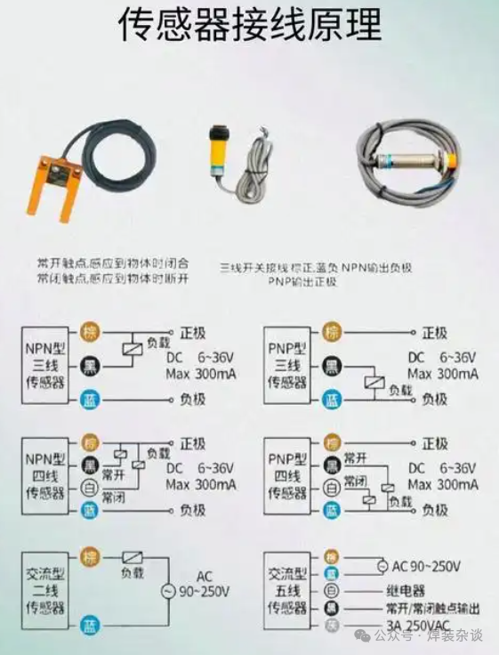
Common Types and Selection Points
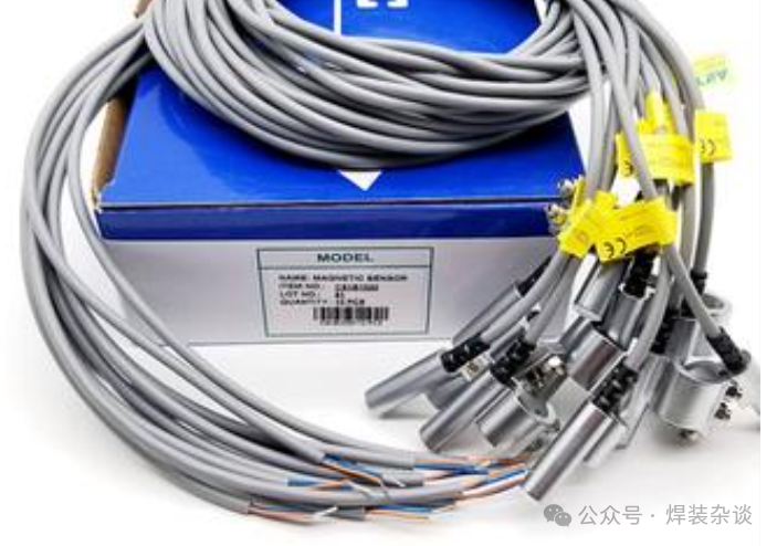
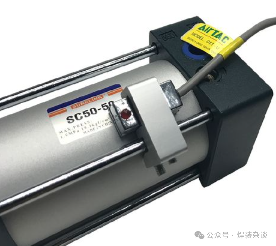
- Magnetic Switch (Reed Switch):
- Application: The absolute mainstay installed on the cylinder body. It determines the extension or retraction state of the cylinder by sensing the magnetic ring on the piston. Extremely low cost, easy to install, and highly reliable.
- Logic: “Detected cylinder extension signal” + “Detected cylinder retraction signal” = confirmation of a complete action cycle.
- Inductive Proximity Sensors:
- Application: Detects the position of metal parts or fixture mechanisms. For example, it detects whether the positioning pin is in place or whether the pressing arm has descended. Since it only senses metal, it has stronger anti-interference capabilities than photoelectric sensors.
- Features: Non-contact, long lifespan, high response frequency.
- Photoelectric Sensors:
- Application: Detects non-metal or any opaque objects. Commonly used for material rack out-of-stock alarms and detecting whether parts obstruct light to determine presence.
- Features: Long detection distance, but easily interfered with by ambient light, dust, and oil, requiring use in clean areas.
System Logic: The PLC program will set strict interlock conditions. For example: “Only when all positioning pin signals are ON, and all clamping cylinder signals are ON, is it allowed to send the ‘Welding Allowed’ signal to the robot.” This fundamentally avoids major quality accidents caused by welding when parts are not properly positioned or clamped.
03
Pressure Sensors: The Precise Touch for Sensing “Clamping Force”
For critical process points, knowing “it is clamped” is not enough; it is also necessary to know “is it clamped with enough force?” Pressure sensors convert invisible forces into quantifiable electrical signals.
Application Scenarios and Logic
- Sheet Metal Pressing/Edging Stations: Monitors whether the pressing force is within the required range to ensure uniform edging quality and avoid crushing or insufficient pressing.
- Clamping Force Monitoring at Key Positioning Points: For large, easily deformable parts (such as side panels and doors), excessive clamping force can lead to part deformation, causing dimensional deviations after welding due to rebound; too little force will not secure the part. Pressure sensors are essential for achieving precise force control.
- Pneumatic System Monitoring: Monitors the main air line pressure; if the pressure drops below the required value (e.g., 0.5MPa), it immediately alarms, prompting maintenance personnel to check the air source to avoid quality issues such as false welding due to insufficient pressure.
Common Types
- Pneumatic Pressure Sensors: Directly installed in the pneumatic pipeline, monitoring the pressure values in the front or rear chamber of the cylinder in real-time.
- Force Sensors: Typically installed between the pressing head and the drive mechanism, directly measuring the force applied to the part.
System Logic: The PLC or dedicated controller will set an upper and lower limit window for pressure. When the sensor feedback value is within this window, the system judges it as qualified; if it exceeds the limit, it immediately triggers an alarm and stops the production line to prevent defective parts from being produced.
04
Vision Sensors: Bestowing the “Recognition and Guidance” of Intelligent Eyes
The vision system is a higher-level “eye” that is not satisfied with just “presence/absence” or “force magnitude”; it can “see” and “understand” images, performing complex positioning and recognition.
Application Scenarios and Logic
- Part Model Recognition (OCR/OCV): In workshops with mixed-line production, it automatically recognizes the current vehicle model by reading the QR code or characters on the part, calling the corresponding robot welding program and fixture control program. This is key to achieving flexible production.
- Robot Vision Guidance:
- Loading Guidance: Guides the robot to accurately grasp randomly placed parts.
- Online Compensation: Before welding, the camera precisely locates feature points on the part, comparing the actual position of the part with the theoretical model, calculating deviations (ΔX, ΔY, ΔZ, ΔRot), and sending this deviation value to the robot. The robot real-time corrects the original welding path, compensating for welding position inaccuracies caused by part or fixture deviations. This is the ultimate tool for improving the dimensional accuracy of the white body.
- Welding Quality Inspection: Conducts preliminary automatic checks on the height of the welded studs, the position of the weld points, and the appearance of the weld seams.
05
Conclusion: Collaborative Operations to Build a Reliable Closed Loop
In modern welding fixture systems, these sensors do not work in isolation but collaborate to construct a multi-layered, highly reliable control closed loop:
- Position Sensors: Form the most basic safety net, ensuring actions are executed correctly.
- Pressure Sensors: Provide quantitative assurance at critical process points, ensuring process stability.
- Vision Sensors: Stand at the top of the system, performing intelligent recognition and active compensation, enhancing the flexibility and precision of the entire system.
The rigorous logical chain dictates that: Without sensor feedback, an automated production line is like running in the dark; the faster the speed, the greater the risk.
Proper selection, correct installation, and careful maintenance of these “eyes” are core tasks for fixture engineers and automation engineers to transform the production line into a highly efficient, reliable, and intelligent “unmanned” dark factory.


E
N
D

Disclaimer: Unless otherwise specified, all images are sourced from the internet or user submissions, and copyrights belong to the original authors or sources. We are committed to protecting the original authors’ copyrights. If there are any copyright issues, please contact us for resolution.

Click
Share
Let more students see


Previous Issues Review

🔵11. Detailed Explanation of Fixture Design Positioning (Auxiliary Mechanisms)
🔵14. Fixture Design Based on DMU Motion Mechanisms
🔵16. Application of CATIA Parametric Design in Fixtures (2)
🔵17. Considerations for Arc Welding Fixture Design
🔵19. Considerations for Arc Welding Workstation Layout
🔵22. What Equipment is Needed to Make Welding Fixtures?
🔵23. What Tools are Needed to Make Welding Fixtures?