Practical Implementation of STM32 Encoder Mode: Comprehensive Analysis of GM37-545 Motor Speed Closed-Loop Control
In embedded motor control scenarios, the encoder is a core component for achieving precise speed measurement and positioning. Whether it’s for obstacle avoidance in smart cars or the smooth start-stop of electric tailgates in vehicles, it relies on its “precise counting”. Today, we will break down from scratch how to use the STM32 timer’s encoder mode to drive the GM37-545 motor with a Hall encoder for stable speed closed-loop control!

First, understand the core: the “counting logic” of the encoder
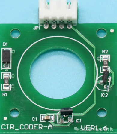
We are using an incremental AB dual-phase encoder, whose counting principle is directly linked to the “number of magnetic poles”. This is key to understanding the subsequent code, so let’s highlight:
1. Number of magnetic poles vs. pulse count
The magnetic ring of the encoder outputs 1 pulse for each pair of magnetic poles (1 N pole + 1 S pole) for both A and B phases—thus, **pulses per revolution = number of magnetic poles × 2 (by default, counting the rising/falling edge of one signal). For example, the motor encoder used in this article has 11 pairs of magnetic poles, calculated as: 11 pairs × 2 = 22 pulses/revolution (this is the conventional definition of “pulse count”).
2. What is PPR?
If you want to improve counting accuracy, you can count the rising edge of phase A, the falling edge of phase A, the rising edge of phase B, and the falling edge of phase B simultaneously—each pair of magnetic poles can count 4 pulses. Thus, the total pulse count for 11 pairs of magnetic poles is 11×4=44, which is the precise definition of “PPR (pulses per revolution)”.
3. Actual pulse count of the reduction motor
The motor reduction ratio is 270 (a key parameter of the GM37-545), meaning that for every revolution of the motor output shaft, the encoder on the motor rotor must turn 270 times. Therefore, the total pulse count per revolution of the output shaft = 11 (number of magnetic poles) × 4 (four-edge counting) × 270 (reduction ratio) = 11880—this value will be directly used in speed calculations!
Second, hardware selection: Key parameters of the GM37-545 motor
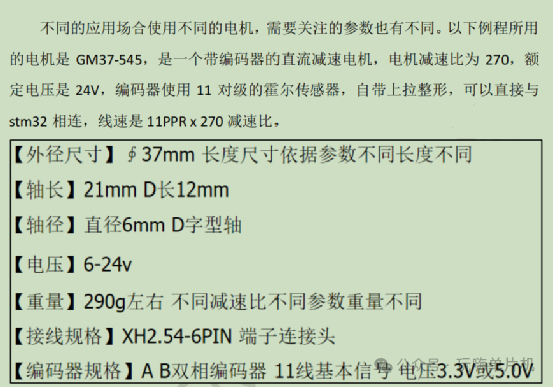
Before practical implementation, it’s essential to understand the hardware details to avoid pitfalls:
Third, STM32 code implementation: From initialization to speed closed-loop
The core objective: to collect encoder pulses through the STM32 timer, calculate the motor speed (RPM), and then adjust the PWM duty cycle through PID to achieve speed closed-loop control. Below is the key code analysis (based on the HAL library):
1. Encoder timer initialization: First, configure the timer for encoder mode to capture A and B phase pulses:
void ENCODER_TIMx_Init(void)
{
ENCODER_TIM_RCC_CLK_ENABLE();
htimx_Encoder.Instance = ENCODER_TIMx;
htimx_Encoder.Init.Prescaler = ENCODER_TIM_PRESCALER;
htimx_Encoder.Init.CounterMode = TIM_COUNTERMODE_UP;
htimx_Encoder.Init.Period = ENCODER_TIM_PERIOD;
htimx_Encoder.Init.ClockDivision=TIM_CLOCKDIVISION_DIV1;
sEncoderConfig.EncoderMode = TIM_ENCODERMODE_TIx;
sEncoderConfig.IC1Polarity = TIM_INPUTCHANNELPOLARITY_BOTHEDGE;
sEncoderConfig.IC1Selection = TIM_ICSELECTION_DIRECTTI;
sEncoderConfig.IC1Prescaler = TIM_ICPSC_DIV1;
sEncoderConfig.IC1Filter = 0;
sEncoderConfig.IC2Polarity = TIM_INPUTCHANNELPOLARITY_BOTHEDGE;
sEncoderConfig.IC2Selection = TIM_ICSELECTION_DIRECTTI;
sEncoderConfig.IC2Prescaler = TIM_ICPSC_DIV1;
sEncoderConfig.IC2Filter = 0;
__HAL_TIM_SET_COUNTER(&htimx_Encoder,0);
HAL_TIM_Encoder_Init(&htimx_Encoder, &sEncoderConfig);
__HAL_TIM_CLEAR_IT(&htimx_Encoder, TIM_IT_UPDATE); // Clear the update interrupt flag
__HAL_TIM_URS_ENABLE(&htimx_Encoder); // Only allow the counter overflow to generate an update interrupt
__HAL_TIM_ENABLE_IT(&htimx_Encoder,TIM_IT_UPDATE); // Enable update interrupt
HAL_NVIC_SetPriority(ENCODER_TIM_IRQn, 0, 0);
HAL_NVIC_EnableIRQ(ENCODER_TIM_IRQn);
HAL_TIM_Encoder_Start(&htimx_Encoder, TIM_CHANNEL_ALL);
}
Key notes:
Set the prescaler to 0: ensure that captured pulses are not divided, ensuring accurate counting;
Select TI1/TI2 mode: simultaneously capture A and B phase pulses, supporting forward and reverse direction detection;
Overflow interrupt: The maximum count of a 16-bit timer is 65535, and when the motor speed is high, it is easy to overflow, requiring the `OverflowCount` variable to extend to a 32-bit count.
2. Overflow interrupt handling: Extend counting range
/****** Encoder timer overflow interrupt service function **********/
void HAL_TIM_PeriodElapsedCallback(TIM_HandleTypeDef *htim)
{
if(__HAL_TIM_IS_TIM_COUNTING_DOWN(&htimx_Encoder))
OverflowCount–; // Count down overflow
else
OverflowCount++; // Count up overflow
}
3. Get 32-bit count value: Avoid overflow errors
/*** Function: Get the encoder’s counter
Return value: @value returns a 32-bit signed count value*/
int32_t YS_Encoder_GetCounting()
{
/* 16bits counter */
uint32_t Value = __HAL_TIM_GET_COUNTER(&htimx_Encoder);
int32_t Period = ENCODER_TIM_PERIOD + 1;
/* 16bits timer is prone to overflow */
return Value + OverflowCount * Period;
}
4. System tick interrupt: Calculate speed every 100ms Use the system tick timer (interrupt every 1ms) to calculate the motor speed every 100ms and perform PID adjustment:
/* Function: System tick timer interrupt callback function
Note: Each time a tick timer interrupt occurs, this callback function is entered once
void HAL_SYSTICK_Callback(void)
{
uwTick++;
/* Speed loop period 100ms */
if(uwTick % 100 == 0)
{
Spd_Pulse = YS_Encoder_GetCounting();
Spd_PPS = Spd_Pulse – LastSpd_Pulse;
LastSpd_Pulse = Spd_Pulse ;
/* 11-line encoder, 270 reduction ratio, one revolution pulse signal is 11*270*4 = 11880 */
Spd_RPM = ((((float)Spd_PPS/(float)PPR)*10.0f)*(float)60);
/* Calculate PID result */
if(Start_flag == 1)
{
PWM_Duty = SpdPIDCalc(Spd_RPM);
/* Determine the current motion direction */
if(PWM_Duty < 0)
{
Motor_Dir = CW;
BDDCMOTOR_DIR_CW();
SetMotorSpeed(-PWM_Duty);
}
else
{
Motor_Dir = CCW;
BDDCMOTOR_DIR_CCW();
SetMotorSpeed(PWM_Duty);
}
}
printf(“ Spd: %.2f r/m \n”,Spd_RPM);
}
}
Speed formula key point: If your motor parameters differ, simply replace “total pulses per revolution”—the formula is universal: `Spd_RPM = (Spd_PPS / total pulses per revolution) × 10 × 60` (10 is for 1/0.1s, and 60 is the conversion factor from seconds to minutes)
Conclusion
The encoder mode of the STM32 timer is a “cost-effective choice” for achieving precise motor speed measurement—no additional hardware is needed, and pulse capture, speed calculation, and closed-loop control can be completed through software configuration. If your project also uses encoder motors, feel free to share your selection and debugging experiences in the comments; the core of embedded development is “theory + practice”. Following this article step by step, you too can quickly master the application of encoder mode~ Like and bookmark, so you won’t get lost in the next motor debugging!