
Power Integrity (PI)
Power Integrity (PI) refers to the verification of whether the voltage and current at the power source and destination meet the requirements. Currently, power integrity remains one of the biggest challenges in high-speed PCB design.
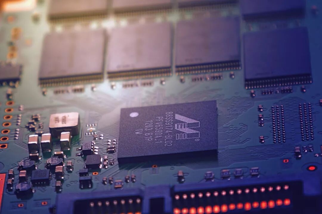 Power integrity involves aspects at the chip level, chip package level, circuit board level, and system level. Among these, the power integrity at the circuit board level must meet the following three requirements:1. The voltage ripple at the chip pins should be minimized (for example, the error between the voltage and 1V should be less than +/-50 mV);2. Control ground bounce (also known as synchronous switching noise SSN, synchronous switching output SSO);3. Reduce electromagnetic interference (EMI) and maintain electromagnetic compatibility (EMC): The power distribution network (PDN) is the largest conductor on the circuit board, making it the easiest to emit and receive noise.
Power Integrity Issues
Power integrity issues are primarily caused by improper design of decoupling capacitors, severe loop effects, poor segmentation of multiple power/ground planes, unreasonable ground layer design, and uneven current distribution. By simulating power integrity, these issues can be identified, and the following methods can be used to resolve power integrity issues:(1) Adjusting the PCB stack-up line width and dielectric layer thickness to meet characteristic impedance requirements, modifying the stack structure to ensure short return paths for signal lines, and adjusting the segmentation of power/ground planes to avoid important signal lines crossing segments;(2) Conducting power impedance analysis on the power used on the printed circuit board, adding capacitors to keep it below the target impedance;(3) Adjusting the positions of components in areas with high current density to allow current to flow through wider paths.
Power Integrity Analysis
In power integrity analysis, the main simulation types include DC drop analysis, decoupling analysis, and noise analysis. DC drop analysis includes analyzing complex routing and plane shapes on the PCB to determine how much voltage is lost due to the resistance of copper.
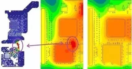 ▲ Shows the current density and temperature map of “hot spots” in PI/thermal co-simulationDecoupling analysis typically drives changes in the values, types, and quantities of capacitors used in the PDN. Therefore, it needs to include capacitor models with parasitic inductance and resistance.The types of noise analysis may vary. They can include noise propagating around the circuit board, noise from IC power pins, which can be controlled by decoupling capacitors. Noise analysis can investigate how noise couples from one via to another and analyze synchronous switching noise.
(The content is organized from the internet.)
Terminology 46

Screenshots from some electronic books
【Complete Set of Hardware Learning Materials Collection】