This software can be used to write PLC programs in languages such as LAD and SFC, calling internal components like cylinders and motors, and simulating real actions through PLC program I/O mapping.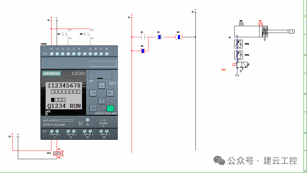 The image below shows an electrical schematic diagram of a Siemens LOGO input terminal connected to a button and an output terminal connected to a solenoid valve, with corresponding I/O signal responses displayed in the LOGO’s LED window.
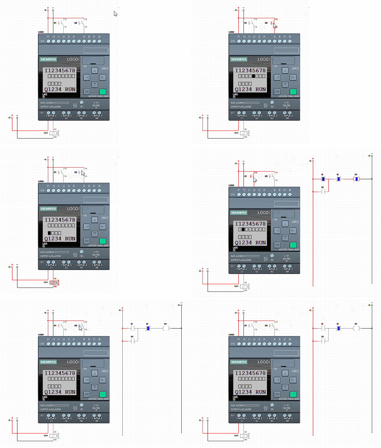
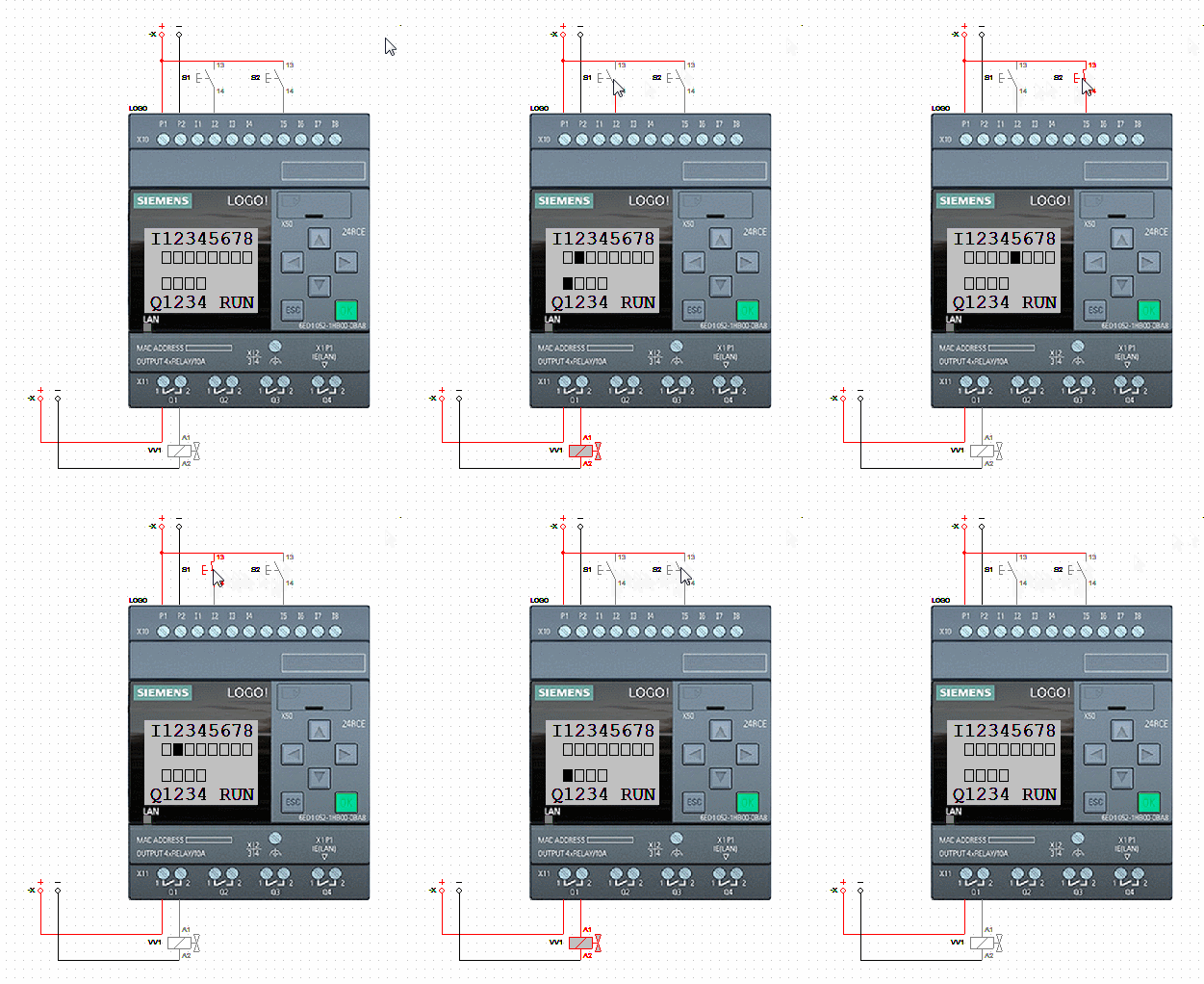 This is an enhancement of the previous diagram, where a ladder diagram program is added to implement a self-locking program for the solenoid valve.
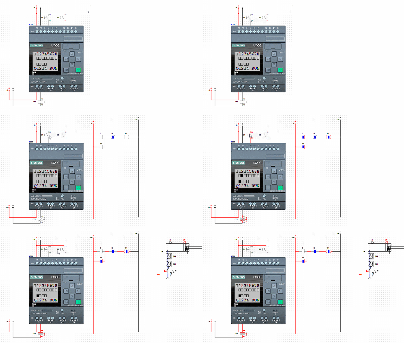
 Based on the circuit and program, an online simulation of a 2-position 3-way solenoid valve controlling the cylinder’s action has been simulated.
 Download Steps: