01
Autonomous Driving Camera – Connection Topology

Camera Connection Topology
Based on the different connection methods between the camera and the main control ECU, the system topology can be divided into the following categories: Point-to-Point Direct Connection Topology、Multiplexing Topology and Daisy Chain Topology。
Point-to-Point Direct Connection Topology
Structure Overview: Point-to-Point topology is the simplest and most intuitive connection method: each camera module is directly connected to the main controller (usually a domain controller or central gateway) via an independent high-speed link. This link is actually composed of a pair of Serializer-Deserializer (SerDes) chips and a coaxial/twisted pair cable. Each camera has its own dedicated transmission channel, conceptually similar to treating the camera as an endpoint device directly connected to the ECU. Traditionally, most early ADAS camera deployments used point-to-point connections, such as a front-facing monocular camera directly connected to the ADAS ECU via a single FPD-Link or GMSL; a rearview camera connected to the vehicle’s main unit via a single video link, etc.
Advantages: The advantage of point-to-point topology lies in its simple architecture, low latency, and non-interference. Each camera enjoys dedicated bandwidth, and its output is sent directly to the main control processor, eliminating the reuse/scheduling delay at intermediate nodes. Therefore, it can achieve the lowest end-to-end latency and high real-time performance, which is especially beneficial for safety-critical sensors like front-facing cameras. At the same time, each link is physically isolated, so a fault in one link (such as a cable short or break) does not affect other cameras, providing inherent fault isolation. In systems that need to meet ASIL functional safety, this isolation helps simplify safety analysis and redundancy design. Additionally, point-to-point architecture does not require complex aggregation switch logic, making both hardware and software implementation relatively straightforward, and debugging is easier to pinpoint issues.
Disadvantages: The main disadvantage of this topology is that as the number of cameras increases, the number of harnesses and interfaces expands. Each additional camera requires a new high-speed cable from the camera to the ECU, as well as an additional SerDes receiving port on the ECU (or the use of multi-channel deserializer chips). For a typical L3 configuration with 8 to 12 cameras, if fully connected point-to-point, the harness weight and cost will significantly increase, and the ECU needs enough MIPI CSI-2 interfaces to connect all video streams. Many general-purpose SoCs have a limited number of CSI interfaces (commonly 2 to 4), so fully direct connections often require additional use of FPGAs or bridging chips to expand interfaces, increasing design complexity. In terms of harness layout, having over ten coaxial cables running through the vehicle also occupies space and increases the difficulty of overall vehicle wiring.
Usage Scenarios: Point-to-point topology is suitable for scenarios with fewer cameras or extremely high latency requirements. For example, a single front-facing camera plus a few surround cameras in an L2 system can meet the needs with 3 to 5 cameras directly connected to the SoC. In some distributed architectures, the front-facing camera with built-in computing chips like Mobileye processes data independently without aggregation, so it only needs minimal direct communication with the main control. Point-to-point is also commonly used in prototype development and testing phases due to its simple structure and ease of performance verification. In applications that demand extremely low latency (such as collision avoidance emergency braking), the video from the front-facing camera is usually directly captured and processed by the SoC interface without going through other intermediate nodes.
Multiplexing Topology
Structure Overview: Multiplexing (also known as Hub or Star topology) uses a hub/multiplexer to aggregate multiple camera videos to the main control. Specifically, an intermediate node (usually near the main control ECU) is added to the vehicle, which contains multi-channel deserializers or switching chips that can simultaneously receive serial data from multiple cameras and output it to the central SoC in an appropriate interface format. A classic example is TI’s DS90UB960-Q1, which can connect 4 FPD-Link cameras and output to the processor via 2 CSI-2 channels, as shown in Figure 1. Another example is Maxim’s MAX9296 GMSL deserializer, which can connect 2 6Gbps GMSL2 cameras and aggregate to a 4-channel CSI-2 output, as shown in Figure 2. The multiplexing topology effectively forms a star network centered around the deserializer hub: each camera sends data to the center, which processes it and delivers it to the main control.
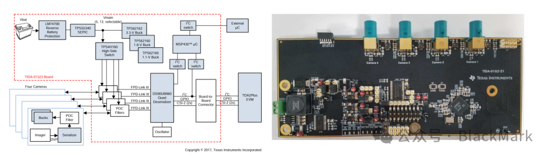
Figure 1
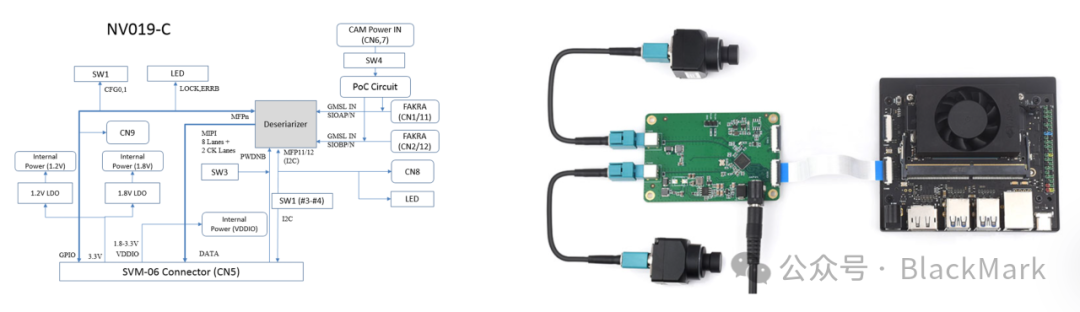
Figure 2
Advantages: The greatest advantage of the multiplexing architecture is the significant reduction in harness and interface requirements. Up to 4 camera videos can be concentrated through a single aggregation node and connected to the SoC with fewer high-speed interfaces. This means that for an 8-camera system, only 2 high-speed output buses (each carrying 4 virtual channels) are needed to enter the SoC, rather than 8 separate buses. This simplifies the design of the main control SoC and reduces the requirements for the number of CSI interfaces and bandwidth. For example, the TI TDA4VM has 2 CSI interfaces, and with 2 UB960 hubs, it can support 8 camera inputs. In terms of harness, the wiring length from the cameras to the hub is generally shorter, reducing the total length of the bus and concentrating the wiring. Additionally, the aggregation node can be responsible for camera synchronization and timing management. For instance, the UB960 supports sending synchronization trigger signals to 4 cameras to ensure frame synchronization, facilitating multi-camera fusion by the main control. The aggregation node also has the opportunity to perform preliminary data preprocessing (such as frame cropping, selective transmission) and error detection, which alleviates the burden on the SoC and enhances system robustness. Overall, the multiplexing topology is scalable and suitable for designs with a larger number of cameras.
Disadvantages: Introducing an aggregation hub also brings some trade-offs: first, the video streams must pass through the hub for aggregation before output, which introduces additional processing latency. Although these chips mostly use parallel processing and high-speed switching, the latency is in the microsecond range, but it still adds a hop time compared to direct connections. Secondly, the hub becomes a single point of bottleneck, and its output total bandwidth limits the overall system bandwidth ceiling. For example, the UB960 single-channel CSI-2 output supports a maximum of 4×CSI lanes @ 1.6 Gbps each, approximately 6.4 Gbps, which is close to full load when connecting 4 2MP@60fps cameras. If the camera resolution increases, it may be necessary to increase the number of hubs or upgrade versions. Thirdly, as a centralized node, the hub has a higher risk of single-point failure. If the hub fails, all camera signals under its jurisdiction will be lost. Therefore, in high-safety-requirement scenarios, dual-redundant hubs or other compensatory measures may be needed. Finally, using a hub increases hardware costs and design complexity, as each hub chip and its power supply and heat dissipation need to be carefully considered. However, with the trend of vehicle domain control, aggregating perception sensors to regional controllers is a trend, so the hub architecture is considered to align with the future development direction of E/E architecture.
Usage Scenarios: The multiplexing topology is very suitable for surround systems and multi-camera fusion applications. In a typical 360° surround view, 4 fisheye cameras at the corners of the vehicle are concentrated through a hub into a single video sent to the GPU for stitching, thereby reducing SoC interface occupancy and ensuring synchronization. For example, dual cameras for driver monitoring (DMS) and occupant monitoring (OMS) can also be merged into a single USB/CSI input to the main control using a dual-input hub, improving system integration. L3 autonomous driving typically has up to 8 to 12 cameras, and using 2 to 3 four-channel hubs to concentrate into a central computing platform is a more economical solution. In a domain controller architecture, a vehicle-mounted perception domain controller often connects several hub modules to manage different directional cameras (front view, surround view, etc.), reducing harnesses and facilitating modular partition design.
Daisy Chain Topology
Structure Overview: Daisy Chain topology refers to multiple camera modules connected in series on the same communication link, with signals transmitted step by step along each node, similar to a string of beads. Specifically, this may be implemented through a special multi-node SerDes protocol (such as A-PHY) or by adding forwarding functions within the camera modules to continue passing upstream data to the next node. In a daisy chain network, often only the last-level node is directly connected to the main control ECU, while intermediate nodes are connected to each other through “cascade ports”. For example, in a certain scheme, the left front and left rear cameras are connected in series: the left rear camera sends video to the left front camera, which then sends the combined signal to the main control. This way, the two cameras share a long cable, and the signal is relayed once along the way.
Advantages: The outstanding advantage of daisy chain topology is the further reduction in harness and interface occupancy. Multiple cameras can share the same physical path, eliminating the need to wire each camera separately to the ECU, thus saving a significant amount of wiring and connectors. This is particularly beneficial for larger vehicles (such as trucks and buses) and densely populated areas (such as the sides of the vehicle). Additionally, due to the series connection of nodes, sharing the bus also makes the topology more flexible for expansion—adding new cameras to the existing chain only requires attaching a new node at the end, without needing new ECU ports. Theoretically, this also aids in future modular plug-and-play upgrades. For certain dual-camera combinations (such as front-facing stereo cameras), if they can be output together through a daisy chain, it can ensure synchronization and reduce interface requirements. The A-PHY standard emphasizes support for daisy chains based on this consideration.
Disadvantages: However, the daisy chain architecture also brings challenges and limitations: first, the more nodes on the link, the higher the total bus bandwidth occupancy, as all nodes share a single high-speed link, and the total bandwidth requirement is the sum of all cameras. Therefore, the practicality of daisy chains is limited by the maximum link rate and scheduling efficiency. For example, A-PHY single link 16 Gbps may barely support 3 2K cameras in series, but more than that becomes difficult. Secondly, a single point of failure on the daisy chain has a large impact range. If a certain intermediate node or connection on the chain fails, all subsequent nodes’ video cannot reach the main control. This is more fragile than multiplexing topology, so redundant paths (such as ring bidirectional) need to be designed to enhance reliability. Thirdly, implementing a daisy chain requires camera modules or SerDes to have forwarding/arbitration capabilities, allowing each node to handle data frames not belonging to itself and correctly pass them downstream. This increases the complexity and cost of the nodes (requiring dual-port transceivers or daisy chain transceiver chips). Currently, FPD-Link III and GMSL do not directly support one-to-many daisy chains on the camera side (more commonly used for one-to-many displays), so daisy chain solutions for cameras often require dedicated bridging modules or waiting for mature implementations like A-PHY. Overall, the application practice of daisy chains is currently limited, mostly seen in concept validation or special purposes.
Usage Scenarios: Daisy chain topology has potential applications in in-vehicle displays and certain sensor groups. For example, in multi-display systems: a set of video signals can be connected in series through a daisy chain to drive multiple screens in the front and rear rows, as demonstrated in FPD-Link IV for multi-screen driving in automotive cockpits. In terms of cameras, MIPI A-PHY is expected to be used for side multi-camera connections, such as connecting two or three small cameras on the side of the vehicle in a series to send to the main control for synthesizing a complete side view. There are also ideas to connect four corner cameras in a daisy chain for overhead surround view, reducing downward wiring. However, considering safety and bandwidth, daisy chains are still not common in mass-produced vehicles, more often seen in concept validation stages. Overall, daisy chains are suitable for scenarios where camera distribution is linear, bandwidth is sufficient, and reliability needs to be carefully balanced by designers. Once future SerDes standards and components are perfected, daisy chains may play a greater role in reducing harness costs.
Combining the above comparisons, in L2/L3 system design, generally a small number of key cameras (such as front-facing) can use point-to-point to ensure the lowest latency and high independent safety; a large number of surround/side cameras can be connected through aggregation hubs to reduce harnesses and facilitate centralized processing; if there are special topology requirements or harness-constrained areas, daisy chain solutions can be attempted, but reliability and bandwidth margins must be fully verified. Currently, mainstream implementations often adopt a “point-to-point + aggregation” hybrid architecture: key cameras are directly connected, while ordinary cameras are aggregated into the ECU through hubs. This architecture is relatively robust in engineering, balancing performance and cost.
Main Control SoC Interface Requirements:
In point-to-point solutions, the SoC must have a sufficient number of high-speed camera interfaces (such as MIPI CSI-2 receivers). For example, directly connecting 8 cameras requires the SoC to support 8-channel CSI input or expand through external FPGAs, which is a significant challenge for the SoC.
In aggregation solutions, multiple video streams are aggregated into a few inputs, so the SoC needs to support virtual channels or multiplexed stream parsing capabilities. Most automotive-grade SoCs (such as TI TDA4, NXP S32V, etc.) support MIPI CSI-2 virtual channels, allowing multiple camera streams to be received simultaneously on a single interface. However, attention must be paid to the total bus bandwidth limit of the SoC CSI interface, such as whether each CSI supports over 2Gbps to carry multiple 720p/1080p videos. Some high-end SoCs are equipped with dual-core ISPs or multiple CSI controllers specifically to handle multiple video inputs from hubs.
In daisy chain solutions, the SoC still sees a single interface, but the data volume it carries may be large, so the SoC interface needs to have ultra-high bandwidth margins and support link-layer address resolution/routing. Currently, SoCs generally do not directly support multi-node SerDes protocols (such as A-PHY link layer), so often a deserializer hub is needed to translate the daisy chain bus into a format recognizable by the SoC. This makes the SoC requirements similar to aggregation situations, needing the ability to unpack multiple data streams. As future SoCs integrate A-PHY transceivers, they will also incorporate management logic for daisy chain communication.
Overall, the choice of topology structure needs to match the capabilities of the SoC: SoCs with rich interfaces can use more direct connections; otherwise, external hubs should be used for aggregation; and adopting daisy chains requires new support from SoCs/transceivers. During the design phase, comprehensive consideration of SoC resources, the number of cameras, functional safety, and costs should be made to determine the best topology solution.