Why Understand the SWD Debug Interface?
Debugging is the most critical part of microcontroller development. Early JTAG interfaces required 4-5 wires, occupying too many pins. In contrast, the SWD (Serial Wire Debug) interface only requires 2 essential signal lines, saving PCB space while providing better debugging speed and stability. Currently, almost all ARM Cortex series microcontrollers support SWD debugging.
Basics of SWD Interface
Signal Line Definitions
- SWDIO: Bidirectional data line for exchanging debugging data between the host and target board
- SWCLK: Clock signal line provided by the host (debugger)
- GND: Signal ground
- SWRST (optional): Reset signal
- 3.3V (optional): Power supply
Why is it Better than JTAG?
- Fewer Pins: Only requires 2 essential signal lines
- Faster Speed: Uses synchronous serial communication for high transmission efficiency
- Better Reliability: Strong anti-interference capability, less prone to communication errors
- Lower Cost: Simple interface, cheaper debugger
Practical Application Cases
1. Minimal System Connection Diagram
        ST-LINK v2         Target Board
        ┌────────┐      ┌────────┐
        │        │      │        │
   GND ─┤      1├──────┤GND     │
SWDCLK ─┤      2├──────┤SWDCLK  │
 SWDIO ─┤      3├──────┤SWDIO   │
   3.3V─┤      4├──────┤3.3V    │
        └────────┘      └────────┘
2. Debugger Selection
Currently, mainstream SWD debuggers include:
- ST-LINK: Official ST debugger, best used with STM32
- J-LINK: Produced by SEGGER, powerful but relatively expensive
- DAP-LINK: Open-source solution, cost-effective
Common Issues and Solutions
- Unable to Connect to Target Board
-
Check if the power supply is normal
- Confirm that the signal lines are connected correctly
- Verify if the target chip supports SWD
- Program Download Failed
Reduce SWD clock frequency
- Shorten the length of the connection lines
- Check if the target chip is write-protected
- Debugging Unstable
Add pull-up resistors (recommended 10K)
- Use shielded cables
- Ensure reliable ground connection
Practical Debugging Tips
- Wiring Suggestions
-
Keep SWDIO and SWCLK traces as short as possible
- Avoid high-frequency signal interference
- Add decoupling capacitors if necessary
- Interface Protection
Add TVS diodes for ESD protection
- In-series current-limiting resistors (recommended 22Ω)
- Use opto-isolators if necessary
- Improving Debugging Efficiency
Reserve test points
- Add status indicator LEDs
- Design an independent download interface
Advanced Applications
- Implement Asynchronous Serial Port Multiplexing
- SWD interface can be reused as UART when idle
- Requires correct GPIO mode switching in the program
- High-Speed Data Acquisition
- Use SWD for real-time data monitoring
- Supports online variable read/write
Practical Recommendations
- Reserve a standard 2.54mm pitch 5-pin SWD interface during PCB design
- Add power indication and communication status LEDs
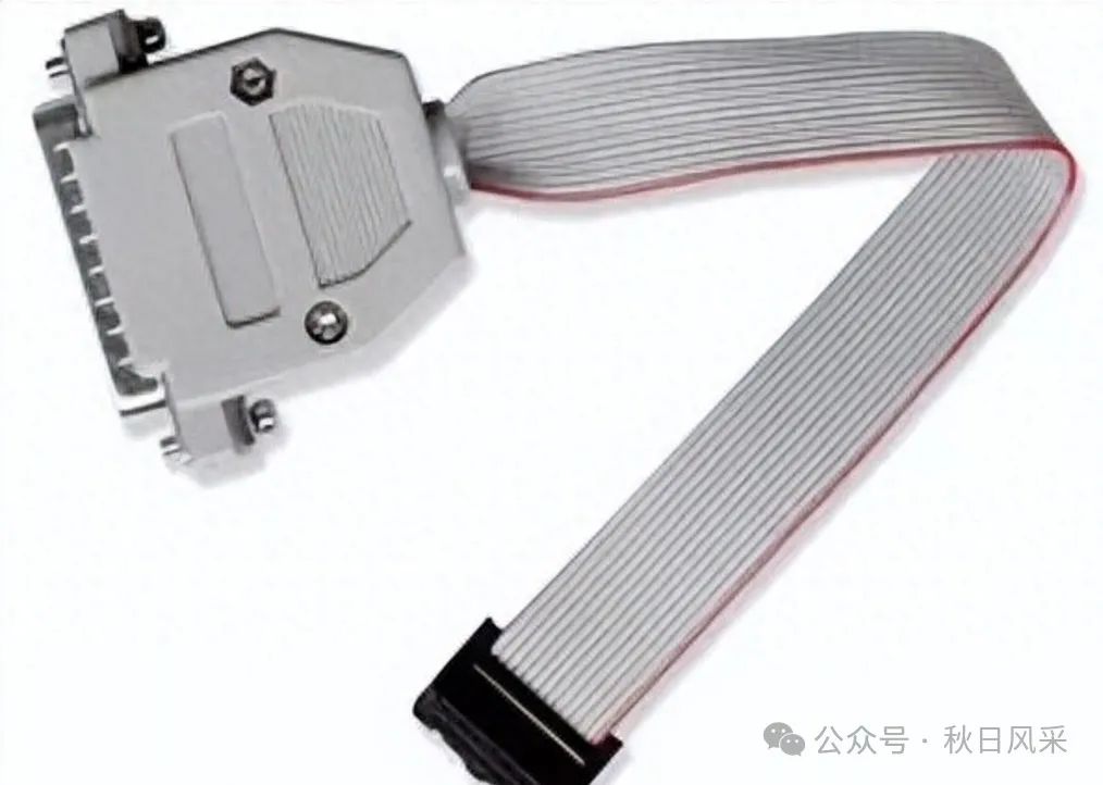
- Prepare a high-quality connection cable
- Master basic oscilloscope operations for troubleshooting
Precautions
- Never connect or disconnect connectors while powered
- Pay attention to level matching (usually 3.3V)
- Prevent signal reversal at the interface
- Keep connectors clean
- Regularly check for reliable contact
Modern microcontroller development relies on efficient debugging methods. With its simple and reliable characteristics, SWD has become a standard in embedded development. Mastering SWD debugging technology can significantly improve development efficiency.