
Introduction:
Recently, I stumbled upon a news article about a development board launched for a chip by Zhou Ligong in my social circle. With a try-it-out attitude, I applied for it, as I happen to have some projects that may utilize it. I would like to thank Mr. Zhang, Manager Dong, and Engineer Ping from Zhiyuan for their strong support.
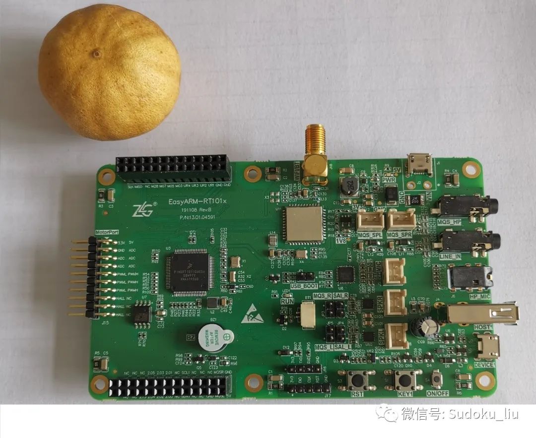
By the way, does anyone have a small orange? I’ve kept one for over a year, and its quality isn’t very good. Has anyone else tried this? Let’s share our experiences. Without further ado, let’s take a look at the chip!
First, let’s talk about the main chip of the development board, the i.MX RT1010
NXP launched the i.MX RT series products based on the Cortex-M7 core in 2017. With the continuous development of this series, NXP introduced the highly cost-effective I.MX RT1010 series products in the fourth quarter of 2019. With a frequency of 500MHz, the commercial-grade RT1010 is priced at only $0.994 for an annual usage of 100K. Currently, products in the market that can reach 500MHz are either very expensive, costing five to six dollars or even eight to nine dollars, or they are small devices that can only achieve 100MHz or below. Achieving such capability at this price point, the i.MX RT1010 is the first of its kind.
i.MX RT1010 Processor Features:
System:
-ARM® Cortex-M7 processor, maximum frequency 500 MHz; -16KB I-Cache, 8KB D-Cache; -Floating Point Unit (FPU), supports VFPv5 architecture; -MPU, supports a maximum of 16 partitions; -128KB I-TCM and D-TCM;
On-Chip Memory:
– 64KB BootROM; – 128KB tightly coupled memory (shared with TCM).
Real-Time Low Latency Response:
– Fastest real-time response with a latency as low as 20ns.
External Storage Interfaces:
– SPI NOR Flash; – Single/Dual/Quad-channel SPI Flash and supports XIP.
Timers:
– 2 general-purpose programmable timers (GPT); – 4-channel periodic interrupt timer (PIT); – 1 FlexPWM.
Audio Interfaces:
– SPDIF input/output interface; – 2 synchronous audio interfaces (SAI), supports I2S, AC97, TDM, and codec applications in DSP interfaces; – MQS interface for medium-quality audio output via GPIO ports.
Analog Interfaces:
– 1 ADC converter (up to 16 channels, one channel cannot be used).
Connectivity:
– USB2.0 OTG controller, chip includes USB-PHY interface; – 4 UARTs; – 2 I2Cs; – 2 SPIs; – 1 FlexIO.
Security:
– Secure JTAG controller (SJC); – High reliability boot (HAB); – Data co-processor (DCP), supports AES-128, SHA-1, SHA256, CRC32 calculations; – FlexSPI, built-in instant AES decryption (OTFAD), supports AES-128, CTR mode, instant QSPI flash decryption; – True Random Number Generator (TRNG); – Secure non-volatile storage (SNVS).
Debug Interfaces:
– ARM CoreSight and Trace components; – Supports JTAG and SWD debug interfaces.
Power Management:
– Fully integrated PMIC, including on-chip DCDC and LDO; – Programmable temperature sensor; – GPC hardware power management controller.
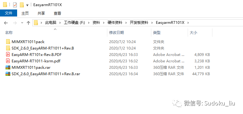
First, let’s see what resources are available:
-
The patch package in the MIMXRT1011pack folder is the DFP file for Keil.
-
SDK_2.6.0_EasyARM-RT1011+Rev.B contains sample code;
-
Two PDF files serve as the user manual for the development board and the schematic of the development board;
Let’s start working on the sample code:
-
First, install the DFP patch package;
-
Open the sample code;
-
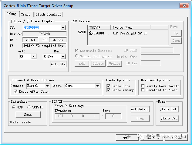
Connect the J-LINK emulator using the SW interface; (Previous articles have detailed explanations, and they are generally similar)
-
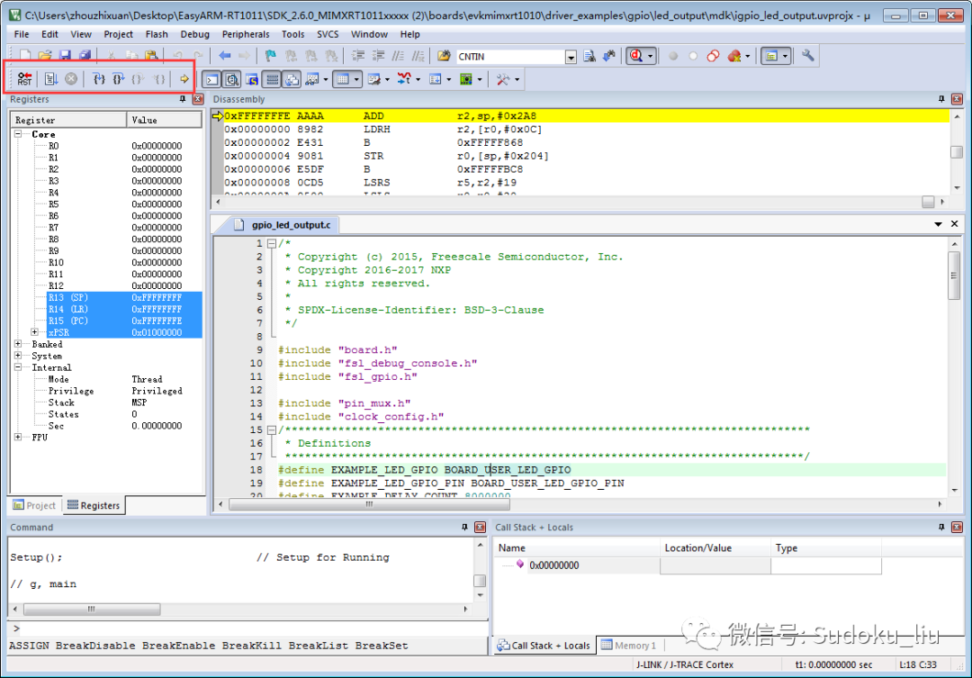
Select the chip, download, simulate, set breakpoints, run at full speed, and observe the effects.
Conclusion:
This chip is suitable for professional microphones. It seems that the sound card I previously made can now reduce costs.