Click on “Microcontroller” at the top, then select “Top/Star“Public Account to receive the latest tweets!
-
Introduction
-
The Autonomous Driving Route Debate: Pure Vision vs. Multi-Sensor Fusion
-
Precise Control of Medical Equipment Using TMC
-
Temperature Monitoring System Circuit Design for Main Drainage Pump Room in Coal Mines_Temperature Sensor Circuit
-
Embedded Class Electronic Circuit Diagram_Circuit Diagram
-
How to Design Overvoltage Protection Circuit?
-
Why Do Microcontrollers Have Multiple VDD?_Embedded Systems and MCU
-
Principle, CTR, and Transfer Delay of Optocouplers_Circuit Diagram
-
Global Semiconductor Market Growth Expected to Drop to 4.6% in 2023, Market Size Reaching $662 Billion
-
With the rapid development of autonomous driving, which will become mainstream: cameras or lidar?
-
Modular Solutions for Building Control Panels
-
Extending the Lifespan of LED Bulbs
-
Considerations for LED Lighting Design in Smart Cities
-
Welcoming the New Star of Machine Condition Monitoring
-
[OpenHarmony IPC Development Board Experience] 2-Setting Up the OpenHarmony Compilation Environment
-
[Meyer MYD-J1028X Development Board Trial Experience] SDK Deployment Instructions
-
[Feilin RZ/G2L Development Board Trial Experience]+03.RZ/V2L Development Board Power-On Test (WIFI + Cross Compilation)
-
Design Implementation of Reading Audio Files and Interface from SD Card Based on MM32F5270 Development Board
-
Design Implementation of GPIO Control to Light Up Based on MM32F5270 Development Board
-
What are the Differences Between J-Link Interface and SWD Interface of J-Link V8 Debugger?
-
How to Read FLASH with ARM Emulator JTAG + SWD?
-
Has anyone summarized the standard circuits for ARM’s JTAG, SWD, and other debugging and programming interfaces?
-
[Feilin RZ/G2L Development Board] 03. Serial Port Parsing Attitude Sensor Data
-
Microcontroller Recruitment Bulletin
-
Microcontroller Project Supply and Demand Information
The Autonomous Driving Route Debate: Pure Vision vs. Multi-Sensor Fusion_Automotive Electronics and Vehicle Networking – Breadboard Community 2022-08-26

The Autonomous Driving Route Debate: Pure Vision vs. Multi-Sensor Fusion
Since General Motors showcased the world’s first autonomous driving concept car in 1939, many tech companies and car manufacturers have continuously integrated sensors, cameras, computing chips, and storage chips into vehicles, experimenting with autonomous driving in specific scenarios like tracks and deserts. Today, manufacturers are gradually introducing autonomous driving into the consumer car market, striving for higher levels of autonomy in this field.
However, we can see that during the advancement of technologies and solutions, there has been a clear “factional dispute” regarding the implementation of autonomous driving. One faction believes in the integration of vision and radar; the other faction argues that pure vision is sufficient. The root of the factional dispute lies in each manufacturer’s unique understanding of autonomous driving, which has yielded varying degrees of success. Of course, through various components available on the Mouser Electronics website for autonomous driving applications, we have also identified some commonalities between the two factions, such as flexible design and performance redundancy.
…… Long press the QR code to access the original text

Precise Control of Medical Equipment Using TMC

Using TMC for Precise Control of Medical Equipment
In today’s rapidly developing society, more and more medical instruments require precise control during low-speed operation, such as infusion pumps, ophthalmic instruments, peristaltic pumps, etc. First and foremost, quality management testing must be prioritized. Trinamic’s solutions have passed SO13485 and ISO9001 certification, converting data information into human motion; precise data can help you manufacture cutting-edge medical devices. This is all thanks to our ability to quickly leverage years of motion control experience and expertise.
Whether at home, in a nursing home, or in an ICU, patients should receive the best rehabilitation care technology. We are committed to enabling health engineers in the medical field to reach their limits, allowing for smaller design solutions and lower indirect costs, fully functional yet energy-efficient drivers, and smooth, quiet motion, which enhances the quality of healthcare and exemplifies the world’s most precise and highly integrated motion control and stepper motor driving technology.
…… Long press the QR code to access the original text

Temperature Monitoring System Circuit Design for Main Drainage Pump Room in Coal Mines_Temperature Sensor Circuit
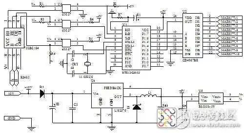
Temperature Monitoring System Circuit Design for Main Drainage Pump Room in Coal Mines
Given the importance of the main drainage pump room in coal mines for mine safety, a temperature monitoring system suitable for the main drainage pump room has been designed. The system adopts a master-slave structure, divided into a detection master station and a collection substation. The collection substation uses the digital temperature sensor MAX6577 to collect and process temperature signals from ten measurement points in the drainage pump room at different times. The detection master station receives temperature data from the substation in real time, enabling functions like temperature display, over-limit alarms, and data storage. Data transmission between the master and slave stations uses the RS485 bus. The system has a simple structure, low maintenance volume, high reliability, and great promotional value. Find component stock on Weiyang Mall.
Hardware Design of the Collection Substation
The collection substation primarily completes temperature measurements for ten measurement points and communicates with the detection master station to transmit temperature data. The substation CPU uses the STC12C2052 microcontroller, which is fully compatible with the internal resources and standard 8051 microcontroller. Since the system’s measurement accuracy requirements are not high, and the drainage pump room…
…… Long press the QR code to access the original text

Embedded Class Electronic Circuit Diagram_Circuit Diagram – Breadboard Community 2022-08-26
Embedded Fingerprint Lock System Circuit Design – Embedded Class Electronic Circuit Diagram
The application fields of embedded fingerprint locks are very broad, including safes, laboratories, and hallway identity verification. This article designs and implements an embedded fingerprint lock based on a fingerprint recognition module, providing a relatively complete software and hardware design scheme. The hardware structure of the fingerprint recognition door lock system mainly includes: fingerprint recognition module, microcontroller, read-write module, power management, and electric lock mechanism, as well as infrared sensing circuits and LCD displays required for the door lock function, where the core part is the fingerprint recognition module and microcontroller. Find component stock on Weiyang Mall.
Microcontroller Door Lock Control Circuit
The core structure of the door lock control is the microcontroller P89LPC932A1, which is a single-chip packaged MCU suitable for many applications requiring high integration and low cost, meeting various performance requirements. The P89LPC932A1 integrates many system-level functions, greatly reducing the number of components, circuit board area, and system costs. The MCU communicates with the fingerprint recognition module via serial port.
…… Long press the QR code to access the original text

How to Design Overvoltage Protection Circuit?_Circuit Diagram – Breadboard Community 2022-08-26
How to Design Overvoltage Protection Circuit?
A simple overvoltage protection circuit can generally be achieved by adding a TVS; when there is a sudden high-energy impact from the outside, it can suppress this energy. Although it can handle high power, even thousands of watts, the duration of suppression is very short. If the device is damaged or if the operating voltage remains above the normal working voltage for a long time, it will be ineffective.
Therefore, the best approach is to design an intelligent circuit, as shown below:
When Vin is at the normal input voltage, the voltage regulator does not undergo reverse breakdown, and the current through R3 and R4 is basically 0. The Vbe of the PNP transistor is 0, meaning the PNP transistor is off. The Vgs of the PMOS transistor Q4 is determined by the voltage divider formed by resistors R5 and R6, allowing the PMOS transistor to conduct, indicating the power supply is functioning normally.
Find component stock on Weiyang Mall.
When Vin exceeds the normal input voltage, Vin > Vb…
…… Long press the QR code to access the original text

Why Do Microcontrollers Have Multiple VDD?_Embedded Systems and MCU – Breadboard Community 2022-08-26
Why Do Microcontrollers Have Multiple VDD?
We know that typical IC components usually have two power pins: one is Vcc or Vdd, and the other is Gnd or Vss. However, modern MCUs often have multiple power pins. What is the reason for this?
Taking a 100-pin MCU as an example, we can see that it has 5 sets of VDD/VSS, and each set of VDD/VSS must be connected. In reality, these multiple VDD pins are interconnected internally. If that’s the case, why don’t chip manufacturers just leave one set exposed? Or, if multiple sets are exposed, can we connect only one set externally? If that’s the case, it would save pin usage and reduce external connection traces.
If only one VDD is connected externally, the current path inside the chip will be relatively long, as shown by the red lines in the figure below.
For high-frequency circuits, the VDD current will experience high-frequency fluctuations (because the higher the frequency, the greater the current required). At this time, the reactance generated along the path will impede the current variation; the longer the path, the greater the reactance, thus the obstruction to the current will become more evident, leading to…
…… Long press the QR code to access the original text

Principle, CTR, and Transfer Delay of Optocouplers_Circuit Diagram – Breadboard Community 2022-08-26
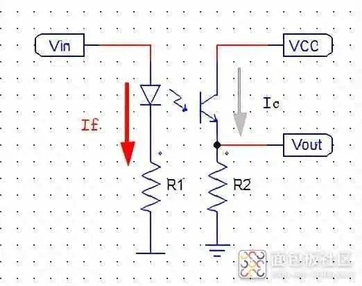
Principle, CTR, and Transfer Delay of Optocouplers
When designing power supplies, we often face a multi-ground system, where different ground loops often require electrical signal interaction, such as between the isolation of the primary and secondary sides of a power supply, and the “upper tube” driving circuit and the power circuit in topologies like full bridge and half bridge. This necessitates the use of isolation methods for electrical signal transmission.
Currently, two common methods are used for isolation in projects: magnetic isolation, where many power supplies use a “driving transformer” to drive the “upper tube,” eliminating the need for a separate auxiliary power supply; and optoelectronic isolation, which is commonly done using optocouplers. However, how do optocouplers work, and what characteristics do they have?
This article will discuss these three aspects in detail: the working principle of optocouplers, the concept of CTR, and the transfer delay of optocouplers.
The working principle of optocouplers…
…… Long press the QR code to access the original text