0 Introduction
Intravenous infusion is one of the most commonly used auxiliary medical methods in clinical medicine. According to statistics, over 80% of hospitalized patients receive intravenous infusion therapy. During the infusion treatment, medical staff select the appropriate infusion speed based on the medication and the patient’s condition. Currently, most hospitals still rely on the experience of medical staff to manually adjust the flow rate regulator of the infusion tube, which introduces significant uncertainty. Additionally, patients, companions, or medical staff need to monitor the remaining medication, increasing the workload of nursing staff and the likelihood of unexpected situations.
This article develops an STM32-based infusion monitoring system to replace manual monitoring. The system uses infrared detection to monitor the droplet falling from the Morpheus drip chamber, controls the droplet speed with a stepper motor and associated transmission device, displays the droplet speed and remaining liquid on an OLED screen, and achieves wireless communication with a PC using a WIFI232 module. By observing the monitoring management software on the host computer, medical staff can grasp the infusion progress of multiple patients in real-time. In case of abnormal situations, a buzzer and LED light will provide audio-visual alarms, allowing relevant personnel to respond promptly. This system not only improves patient comfort during infusion but also enhances the therapeutic effect of intravenous infusion while reducing the workload of nursing staff and alleviating the pressure on medical personnel.
1 System Composition and Working Principle
1.1 System Composition
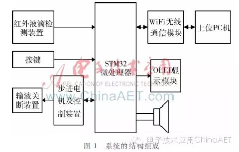
The structure of the STM32-based infusion monitoring system is shown in Figure 1. It mainly includes an infrared droplet detection module, a button module, a stepper motor and its driving circuit, an infusion shut-off transmission device, a wireless communication module, a display module, and an alarm module. The system uses the high-performance, low-power 32-bit microprocessor STM32F103ZET6 as the control core.
1.2 Working Principle
The working principle of the system: In the initial state, the stepper motor controls the transmission device to compress the infusion tube, preventing droplets from falling. Medical staff set the infusion speed based on the properties of the medication and the patient’s condition. The microprocessor controls the stepper motor to rotate clockwise, driving the transmission device’s screw-nut mechanism through a gear set. The transmission device gradually reduces the compression on the infusion tube, allowing more medication to flow through the compression point. The infrared droplet detection module continuously monitors the droplet falling situation, and the detection circuit converts the monitored droplet falling situation into high and low voltage signals for processing by the microprocessor. The microprocessor converts the voltage signals into real-time speed and sets a speed comparison. When the real-time speed equals the set speed, the microprocessor stops the stepper motor, and the connected transmission device also stops moving, maintaining a constant flow rate of the medication through the compression point, thus keeping the infusion speed unchanged. The microprocessor transmits data such as infusion speed, remaining medication, and estimated infusion end time to the PC via the wireless communication module, allowing medical staff to manage the display on the monitoring software interface. Patients can observe the infusion speed and estimated end time through the OLED display module. If necessary, patients can adjust the infusion speed up or down using buttons based on their condition. The microprocessor increases or decreases the infusion speed by controlling the stepper motor to rotate clockwise or counterclockwise. When the remaining medication is below the set value, the microprocessor controls the stepper motor to rotate counterclockwise to shut off the infusion, alerting the patient with a flashing LED light and buzzer, while the monitoring management software highlights the remaining infusion amount to prompt medical staff for action.
2 System Hardware Design
As can be seen from the system composition, the system contains several hardware units. This article focuses on three core units: infrared droplet detection, infusion shut-off, and wireless communication.
2.1 Infrared Droplet Detection
Accurate collection of droplet signals is a prerequisite for calculating the droplet speed. The signal collection must ensure that no drops are missed and must meet hygiene requirements, avoiding contact with the medication. Therefore, infrared photoelectric sensing technology is employed, with the emitting and receiving tubes of the infrared pair installed on either side of the Morpheus drip chamber. When the infrared emitting diode is powered and functioning normally, it emits infrared light that passes through the Morpheus drip chamber and reaches the receiving tube, which converts the received light intensity into current. If there are no droplets falling within the Morpheus drip chamber, the loss of infrared light intensity is small, resulting in a strong current from the receiving tube; conversely, if droplets are falling, the loss of infrared light intensity is significant, leading to a weaker current. Utilizing this principle, the circuit shown in Figure 2 is designed to convert current changes into voltage changes, thereby converting the medication droplet situation into voltage variations.
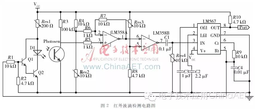
As shown in Figure 2, under a 5V power supply system, the light frequency of the infrared LED is determined by the audio decoder LM567. When there are no droplets falling within the Morpheus drip chamber, the receiving tube can receive the light emitted by the infrared LED, generating a strong current. This current is sufficient to turn on the transistor in the receiving tube, producing a current in the branch where the transistor is located that matches the frequency of the diode branch. After amplification and inversion by the dual operational amplifier LM358, the input signal at pin 3 of the audio decoder LM567 matches the central oscillation signal (the output signal in the figure). According to the working principle of the audio decoder LM567, pin 8 outputs a low level of 0V. When droplets fall within the Morpheus drip chamber, the receiving tube receives some of the light emitted by the infrared LED, generating a weaker current. This current is insufficient to turn on the transistor in the receiving tube. The input signal at U1 of the dual operational amplifier LM358 does not match the frequency of the LED current, thus the input signal at pin 3 of the audio decoder LM567 does not match the central oscillation signal. According to the working principle of the audio decoder LM567, pin 8 outputs a high level of 5V.
As the medication continues to drip, the output port of pin 8 of the audio decoder LM567 forms a standard rectangular wave positive pulse. A low level indicates no droplets falling, while a high level indicates droplets falling. Connecting the output of pin 8 of the LM567 to the I/O port of the STM32, the timer’s input capture function can measure the time interval between two rising edges, which is the time interval between two droplets, thus calculating the droplet falling speed.
2.2 Infusion Shut-off
The system uses a Φ15mm stepper motor and a screw-nut mechanism as the infusion shut-off device. The STM32 microprocessor drives the stepper motor to rotate through the L293D, which also rotates the gear set connected to the stepper motor. The screw-nut mechanism is fixed on the last gear of the gear set. The lateral rotation of the fixed nut causes the nut to move axially as the screw rotates. The infusion shut-off device utilizes the axial movement of the nut to compress the infusion tube, achieving the goal of controlling the infusion speed.
Since the STM32 has limited load capacity and cannot directly drive the stepper motor, it is necessary to add a stepper motor driving circuit between the STM32 and the stepper motor to increase the microcontroller’s load capacity. The system uses the L293D as the driving chip, which fully meets the driving requirements.
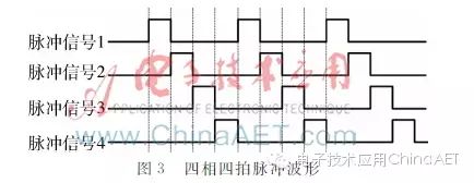
The stepper motor is a purely digitally controlled motor, which can be converted into angular displacement by electrical pulse signals. Since the selected Φ15mm stepper motor is a two-phase four-wire stepper motor, the STM32 must output four pulse signals to control the motor’s rotation phase angle. The four pulse signals must be input according to the working principle of the stepper motor, and this system uses a four-phase four-step pulse input, with the input waveform shown in Figure 3.
2.3 Wireless Communication
The information exchange method between the host computer and the lower computer adopts serial communication, with the communication conversion method using RS232 full-duplex configuration. The asynchronous serial interface of the lower computer STM32 converts signal levels through the communication interface chip MAX3232 to the RS232 standard serial communication circuit, and then the USR-WIFI232 chip achieves bidirectional transparent forwarding of serial to WiFi data packets. The host computer installs a WiFi transceiver module to realize wireless communication. The host computer can send and receive data from multiple lower computers, achieving networked monitoring. The external circuit connection of the wireless communication unit is shown in Figure 4.
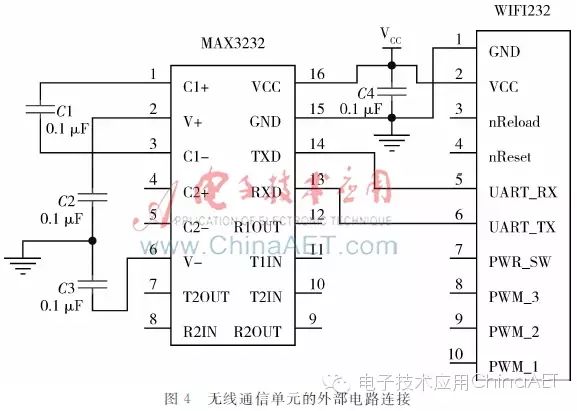
In Figure 4, the external circuit connection of the wireless communication unit allows the host computer to actively query the response signal from the lower computer. If a response is not received once, a query signal is sent again; if no response is received three times in a row, it indicates a system fault, triggering an automatic alarm. If the system responds, both parties enter the data communication state according to the specified communication protocol. This wireless communication unit is safe and reliable, with strong anti-interference capability, and the indoor communication transmission distance can reach 50-60 meters.
3 System Software Design
The software part of the system can be divided into host computer monitoring management software and embedded programs. The embedded program includes the main program, droplet speed measurement, speed control, button settings, OLED display, wireless communication, alarm, and other program units. This article only introduces three key modules: host computer monitoring management software, droplet speed measurement subprogram, and wireless communication subprogram.
3.1 Host Computer Monitoring Management Software
The host computer monitoring management software helps medical staff remotely monitor patients’ infusion status in real-time, allowing them to set and modify relevant parameters to change the infusion process.
The host computer monitoring management software is developed using C# on the VS2013 platform, with its structure shown in Figure 5. The B/S model front-end web service program consists of three parts: system login interface program, system monitoring interface program, and system user operation interface program. Different permissions are applied to logged-in users, leading to different interfaces and operations based on their permissions.
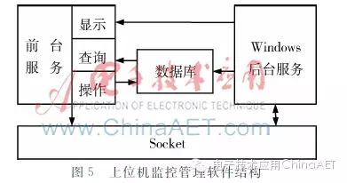
The C/S model Windows backend service program transmits data through Socket communication with WiFi and stores the data obtained from the server in a database using SQL statements, further processing the data to generate visual content for medical staff’s reference, enabling them to make corresponding decisions.
3.2 Droplet Speed Measurement Subprogram
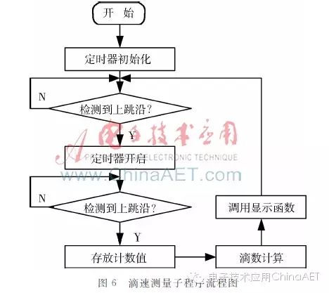
As previously mentioned, the droplet detection circuit converts the droplet falling situation into high and low level signals, where a low level indicates no droplets falling and a high level indicates that droplets have been captured, forming a PWM waveform. The STM32 timer can measure the PWM period. Simply put, the timer starts counting when it detects a rising edge, and when it detects the next rising edge, it stores the current count value in the corresponding channel’s capture/compare register, completing the PWM period measurement.
The period measured by the timer is the time interval between two droplets falling, denoted as T, with a timing precision of 1 ms. For ease of observation, the droplet speed is usually recorded in the unit of: drops/min, thus the formula for calculating droplet speed is: V=60*1000/T. Since the droplet falling situation is easily affected by the environment and fluctuates significantly, to improve the measurement accuracy, the method of continuously measuring three droplets to take the average speed is adopted. Practical results show that this measurement scheme can fully meet the accuracy requirements. The flowchart of the droplet speed measurement subprogram is shown in Figure 6.
3.3 Wireless Communication Subprogram
After the hardware setup is complete, initialization is performed first. The main content of the initialization is to set the baud rate and server IP address, with the system’s baud rate set to 57,600 b/s and the server IP address set to: 10.10.100.254. After initialization, click to establish a TCP connection, and the USR-WIFI232 chip enters monitoring mode, ready for data reception.
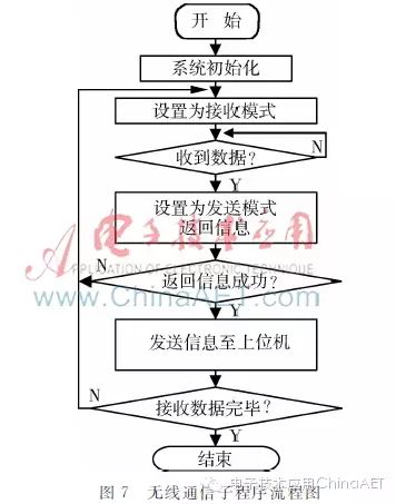
When the USR-WIFI232 chip receives the corresponding carrier signal in the set frequency band and the received address signal matches the program settings, the chip pairs successfully. The chip’s working mode is set to receive, and the host computer transmits data to the STM32 over the WiFi network at the set baud rate. Subsequently, the STM32 transmits the feedback signal to the chip via the RS232 serial port, changing the chip’s working mode to send, and the feedback signal is sent back to the monitoring management software via the WiFi network, completing one cycle. The chip’s working mode is reset to receive, repeating the above process, and the system begins a new cycle to receive new data. The flowchart of the wireless communication subprogram is shown in Figure 7.
This article provides an in-depth analysis of the working principle and implementation details of the STM32-based infusion monitoring system. The system can accurately measure and adjust the droplet speed. It features wireless communication capabilities, achieving multifunctionality and convenience for medical staff to manage centrally, significantly reducing their workload. Test results indicate that the system is safe, reliable, and highly accurate, with broad application prospects.