
There is a small interactive gift at the end of the article, don’t miss it❤️
import sensor, image, time, math,pybfrom pyb import UART
sensor.reset()sensor.set_pixformat(sensor.RGB565)sensor.set_framesize(sensor.QQVGA) # we run out of memory if the resolution is much bigger...sensor.skip_frames(time = 2000)sensor.set_auto_gain(False) # must turn this off to prevent image washout...sensor.set_auto_whitebal(False) # must turn this off to prevent image washout...clock = time.clock()uart = UART(3, 115200)#Serial port baud rate
f_x = (2.8 / 3.984) * 160 # find_apriltags defaults to this if not setf_y = (2.8 / 2.952) * 120 # find_apriltags defaults to this if not setc_x = 160 * 0.5 # find_apriltags defaults to this if not set (the image.w * 0.5)c_y = 120 * 0.5 # find_apriltags defaults to this if not set (the image.h * 0.5)
def degrees(radians):return (180 * radians) / math.pi
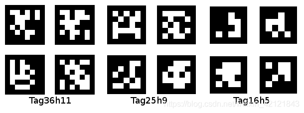
while(True): clock.tick() img = sensor.snapshot()for tag in img.find_apriltags(fx=f_x, fy=f_y, cx=c_x, cy=c_y): # defaults to TAG36H11 img.draw_rectangle(tag.rect(), color = (255, 0, 0)) img.draw_cross(tag.cx(), tag.cy(), color = (0, 255, 0)) print_args = (tag.x_translation(), tag.y_translation(), tag.z_translation())#degrees(tag.x_rotation()), degrees(tag.y_rotation()), degrees(tag.z_rotation()))# Translation units are unknown. Rotation units are in degrees.# print("Tx %f, Ty %f, Tz %f" % print_args) uart.write("A%.2f,B%.2f,C%.2f," % print_args+'\r\n')#Set specific format for STM32 to segment and obtain data#pyb.delay(500)# print(clock.fps())
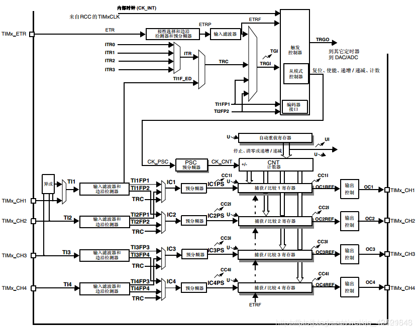

TIM8_PWM_Init(400-1,20-1); //Used to control motors, 168M/20=8.4Mhz counting frequency, reload value is 400, so PWM frequency is 8.4M/400=21Khz. TIM3_PWM_Init(200-1,8400-1);//Used to control servos, 50HZ TIM2_Int_Init(400-1,20-1);//Timer interrupt, 21KHZ TIM7_Int_Init(500-1,8400-1);//Used for encoder counting, 20HZ, interrupt once every 50ms uart_init(115200); //Initialize serial port 1 baud rate to 115200 Encoder_Init_TIM4();//Encoder interface initialization
void uart_init(u32 bound){//GPIO port settings  GPIO_InitTypeDef GPIO_InitStructure;  USART_InitTypeDef USART_InitStructure;  NVIC_InitTypeDef NVIC_InitStructure;
  RCC_AHB1PeriphClockCmd(RCC_AHB1Periph_GPIOA,ENABLE); //Enable GPIOA clock  RCC_APB2PeriphClockCmd(RCC_APB2Periph_USART1,ENABLE);//Enable USART1 clock
//Serial port 1 corresponding pin remapping  GPIO_PinAFConfig(GPIOA,GPIO_PinSource9,GPIO_AF_USART1); //GPIOA9 remapping to USART1  GPIO_PinAFConfig(GPIOA,GPIO_PinSource10,GPIO_AF_USART1); //GPIOA10 remapping to USART1
//USART1 port configuration  GPIO_InitStructure.GPIO_Pin = GPIO_Pin_9 | GPIO_Pin_10; //GPIOA9 and GPIOA10  GPIO_InitStructure.GPIO_Mode = GPIO_Mode_AF;//Multiplexing function  GPIO_InitStructure.GPIO_Speed = GPIO_Speed_50MHz;  //Speed 50MHz  GPIO_InitStructure.GPIO_OType = GPIO_OType_PP; //Push-pull multiplexing output  GPIO_InitStructure.GPIO_PuPd = GPIO_PuPd_UP; //Pull-up  GPIO_Init(GPIOA,&GPIO_InitStructure); //Initialize PA9, PA10
//USART1 Initialization Settings  USART_InitStructure.USART_BaudRate = bound;//Baud rate settings  USART_InitStructure.USART_WordLength = USART_WordLength_8b;//Word length is 8 bits data format  USART_InitStructure.USART_StopBits = USART_StopBits_1;//One stop bit  USART_InitStructure.USART_Parity = USART_Parity_No;//No parity bit  USART_InitStructure.USART_HardwareFlowControl = USART_HardwareFlowControl_None;//No hardware data flow control  USART_InitStructure.USART_Mode = USART_Mode_Rx | USART_Mode_Tx;  //Receive and transmit mode  USART_Init(USART1, &USART_InitStructure); //Initialize serial port 1
  USART_Cmd(USART1, ENABLE);  //Enable serial port 1
  USART_ClearFlag(USART1, USART_FLAG_TC);
#if EN_USART1_RX    USART_ITConfig(USART1, USART_IT_RXNE, ENABLE);//Enable related interrupts
//Usart1 NVIC configuration  NVIC_InitStructure.NVIC_IRQChannel = USART1_IRQn;//Serial port 1 interrupt channel  NVIC_InitStructure.NVIC_IRQChannelPreemptionPriority=3;//Preemptive priority 3  NVIC_InitStructure.NVIC_IRQChannelSubPriority =3;    //Sub-priority 3  NVIC_InitStructure.NVIC_IRQChannelCmd = ENABLE;      //IRQ channel enable  NVIC_Init(&NVIC_InitStructure);  //Initialize VIC register according to specified parameters,
#endif
}
void USART1_IRQHandler(void)                  //Serial port 1 interrupt service program{  u8 Res;#ifdef OS_TICKS_PER_SEC     //If the clock tick count is defined, it indicates that ucosII is to be used.  OSIntEnter();    #endifif(USART_GetITStatus(USART1, USART_IT_RXNE) != RESET)  //Receive interrupt (the received data must end with 0x0d 0x0a)  {    Res =USART_ReceiveData(USART1);//(USART1->DR);  //Read the received data
if((USART_RX_STA&0x8000)==0)//Receiving not completed    {if(USART_RX_STA&0x4000)//Received 0x0d      {if(Res!=0x0a)USART_RX_STA=0;//Reception error, restart else USART_RX_STA|=0x8000;  //Reception completed       }else //Not yet received 0x0D      {  if(Res==0x0d)USART_RX_STA|=0x4000;else        {          USART_RX_BUF[USART_RX_STA&0X3FFF]=Res ;          USART_RX_STA++;if(USART_RX_STA>(USART_REC_LEN-1))USART_RX_STA=0;//Reception data error, restart reception            }           }    }          } #ifdef OS_TICKS_PER_SEC     //If the clock tick count is defined, it indicates that ucosII is to be used.  OSIntExit();                         #endif}
#endif
/*Global variables involved float data[3];//Distances in x, y, z directions, in floating point formatunsigned char data_string[3][7];//Distances in x, y, z directions, in string format*/if(USART_RX_STA&0x8000)    {  //Empty stringfor(i=0;i<2;i++)      {for(j=0;j<6;j++)        {          data_string[i][j]=' ';        }      }      len=USART_RX_STA&0x3fff;//Get the length of the data received this timefor(t=0,j=0;t<len;t++)      {        j=0;if(USART_RX_BUF[t]=='A')        {          t++;//Remove the first letterwhile(USART_RX_BUF[t]!=',')          {            data_string[0][j]=USART_RX_BUF[t];            t++;            j++;          }        }if(USART_RX_BUF[t]=='B')        {          t++;//Remove the first letterwhile(USART_RX_BUF[t]!=',')          {            data_string[1][j]=USART_RX_BUF[t];            t++;            j++;          }        }if(USART_RX_BUF[t]=='C')        {          t++;//Remove the first letterwhile(USART_RX_BUF[t]!=',')          {            data_string[2][j]=USART_RX_BUF[t];            t++;            j++;          }        }      }//Convert string to floating point data[0]=myatof(data_string[0])/100.0;//xdata[1]=myatof(data_string[1])/100.0;//ydata[2]=myatof(data_string[2])*(-1)/100.0;//z, input is negative, convert to positive//USART2 send data//        Usart_SendString( RS232_USART, (uint8_t *)USART_RX_BUF );
//LCD update display//Show xyz//        CLEAR(10);//        Gui_DrawFont_GBK16(30,0,BLACK,WHITE,clear);//        Gui_DrawFont_GBK16(30,0,BLACK,WHITE,data_string[0]);//        Gui_DrawFont_GBK16(30,20,BLACK,WHITE,clear);//        Gui_DrawFont_GBK16(30,20,BLACK,WHITE,data_string[1]);//        Gui_DrawFont_GBK16(30,40,BLACK,WHITE,clear);//        Gui_DrawFont_GBK16(30,40,BLACK,WHITE,data_string[2]);
        USART_RX_STA=0;//Clear the flag bit    }}
int myatof(const char *str)//This function is only suitable for floating point numbers with two decimal places, returns the int value multiplied by 100, as float return has errors{int flag = 1;//Indicates positive numberint res =0;  u8 i=1; //Two decimal places after the decimal pointwhile(*str != '\0')    {if( !(*str >= '0' && *str <= '9'))//Find the first number in the string      {        str++;continue;      }if(*(str-1) == '-')      {        flag=-1;//Indicates a negative number      }
while(*str >= '0' && *str <= '9')    {      res = res *10 + (*str - '0');      str++;    }if(*str == '.')    {      str++;      res = res *10 + (*str - '0');      str++;      res = res *10 + (*str - '0');//Keep two digits, so add twicereturn res*flag;    }}
void LCD_GPIO_Init(void);void Lcd_WriteIndex(u8 Index);void Lcd_WriteData(u8 Data);void Lcd_WriteReg(u8 Index,u8 Data);u16 Lcd_ReadReg(u8 LCD_Reg);void Lcd_Reset(void);void Lcd_Init(void);void Lcd_Clear(u16 Color);void Lcd_SetXY(u16 x,u16 y);void Gui_DrawPoint(u16 x,u16 y,u16 Data);unsigned int Lcd_ReadPoint(u16 x,u16 y);void Lcd_SetRegion(u16 x_start,u16 y_start,u16 x_end,u16 y_end);void LCD_WriteData_16Bit(u16 Data);
void TFT_Init_Show(void){ Lcd_Clear(WHITE); Gui_DrawFont_GBK16(16,70,BLACK,WHITE,"by WILL CHAN"); delay_ms(1000); Lcd_Clear(WHITE); Gui_DrawFont_GBK16(3,0,RED,WHITE,"X:"); Gui_DrawFont_GBK16(3,20,RED,WHITE,"Y:"); Gui_DrawFont_GBK16(3,40,RED,WHITE,"Z:"); Gui_DrawFont_GBK16(3,60,RED,WHITE,"speed:");}
void Gui_DrawFont_GBK16(u16 x, u16 y, u16 fc, u16 bc, u8 *s){  unsigned char i,j;  unsigned short k,x0;  x0=x;
while(*s)   {  if((*s) < 128)     {      k=*s;if (k==13)       {        x=x0;        y+=16;      }else      {if (k>32) k-=32; else k=0;
for(i=0;i<16;i++)for(j=0;j<8;j++)           {if(asc16[k*16+i]&(0x80>>j))  Gui_DrawPoint(x+j,y+i,fc);else            {if (fc!=bc) Gui_DrawPoint(x+j,y+i,bc);            }          }        x+=8;      }      s++;    }
else    {
for (k=0;k<hz16_num;k++)       {if ((hz16[k].Index[0]==*(s))&&(hz16[k].Index[1]==*(s+1)))        { for(i=0;i<16;i++)            {for(j=0;j<8;j++)               {if(hz16[k].Msk[i*2]&(0x80>>j))  Gui_DrawPoint(x+j,y+i,fc);else {if (fc!=bc) Gui_DrawPoint(x+j,y+i,bc);                }              }for(j=0;j<8;j++)               {if(hz16[k].Msk[i*2+1]&(0x80>>j))  Gui_DrawPoint(x+j+8,y+i,fc);else                {if (fc!=bc) Gui_DrawPoint(x+j+8,y+i,bc);                }              }            }        }        }      s+=2;x+=16;    }
}}
//Generic timer 2 interrupt initialization//arr: auto reload value.//psc: clock prescaler//Timer overflow time calculation method: Tout=((arr+1)*(psc+1))/Ft us.//Ft=Timer working frequency, unit:Mhz//Here Timer 2 is used!void TIM2_Int_Init(u16 arr,u16 psc){  TIM_TimeBaseInitTypeDef TIM_TimeBaseInitStructure;  NVIC_InitTypeDef NVIC_InitStructure;
  RCC_APB1PeriphClockCmd(RCC_APB1Periph_TIM2,ENABLE);  ///Enable TIM2 clock
  TIM_TimeBaseInitStructure.TIM_Period = arr;   //Auto reload value  TIM_TimeBaseInitStructure.TIM_Prescaler=psc;  //Timer division  TIM_TimeBaseInitStructure.TIM_CounterMode=TIM_CounterMode_Up; //Up count mode  TIM_TimeBaseInitStructure.TIM_ClockDivision=TIM_CKD_DIV1;
  TIM_TimeBaseInit(TIM2,&TIM_TimeBaseInitStructure);//Initialize TIM3
  TIM_ITConfig(TIM2,TIM_IT_Update,ENABLE); //Allow timer 2 update interrupt  TIM_Cmd(TIM2,ENABLE); //Enable timer 2
  NVIC_InitStructure.NVIC_IRQChannel=TIM2_IRQn; //Timer 2 interrupt  NVIC_InitStructure.NVIC_IRQChannelPreemptionPriority=0; //Preemptive priority 1  NVIC_InitStructure.NVIC_IRQChannelSubPriority=2; //Sub-priority 3  NVIC_InitStructure.NVIC_IRQChannelCmd=ENABLE;  NVIC_Init(&NVIC_InitStructure);
}
void TIM2_IRQHandler(void){ if(TIM_GetITStatus(TIM2,TIM_IT_Update)==SET)//Overflow interrupt {if(motor_flag==1)//Reverse { TIM_SetCompare1(TIM8,motor_duty*PID_val_motor*400.0);//Compare with the timer's auto reload value to set the duty cycle, pin:PC6 TIM_SetCompare2(TIM8,0); }if(motor_flag==0)//Forward { TIM_SetCompare1(TIM8,0); TIM_SetCompare2(TIM8,motor_duty*PID_val_motor*400.0);//Compare with the timer's auto reload value to set the duty cycle, pin:PC7 } TIM_SetCompare1(TIM3,200-(servo_angle/45.0+1)*5);//Set servo angle, pin:PA6 } TIM_ClearITPendingBit(TIM2,TIM_IT_Update); //Clear interrupt flag}
void TIM8_PWM_Init(u32 arr,u32 psc){                //This part needs manual modification of IO port settings
  GPIO_InitTypeDef GPIO_InitStructure;  TIM_TimeBaseInitTypeDef  TIM_TimeBaseStructure;  TIM_OCInitTypeDef  TIM_OCInitStructure;  TIM_BDTRInitTypeDef  TIM_BDTRInitStructure;
  RCC_APB2PeriphClockCmd(RCC_APB2Periph_TIM8,ENABLE);    //Enable TIM8 clock      RCC_AHB1PeriphClockCmd(RCC_AHB1Periph_GPIOA|RCC_AHB1Periph_GPIOB|RCC_AHB1Periph_GPIOC, ENABLE);   //Enable PORTA clock
  GPIO_InitStructure.GPIO_Pin = GPIO_Pin_7;           //GPIOFA  GPIO_InitStructure.GPIO_Mode = GPIO_Mode_AF;        //Multiplexing function  GPIO_InitStructure.GPIO_Speed = GPIO_Speed_50MHz;  //Speed 100MHz  GPIO_InitStructure.GPIO_OType = GPIO_OType_PP;      //Push-pull multiplexing output  GPIO_InitStructure.GPIO_PuPd = GPIO_PuPd_UP;        //Pull-up  GPIO_Init(GPIOA,&GPIO_InitStructure);              //Initialize PA7
  GPIO_InitStructure.GPIO_Pin = GPIO_Pin_0|GPIO_Pin_1;  GPIO_Init(GPIOB,&GPIO_InitStructure);
  GPIO_InitStructure.GPIO_Pin = GPIO_Pin_6|GPIO_Pin_7|GPIO_Pin_8;  GPIO_Init(GPIOC,&GPIO_InitStructure);
  GPIO_PinAFConfig(GPIOC,GPIO_PinSource6,GPIO_AF_TIM8); //GPIOA8 remapping to timer 1  GPIO_PinAFConfig(GPIOC,GPIO_PinSource7,GPIO_AF_TIM8); //GPIOA9 remapping to timer 1  GPIO_PinAFConfig(GPIOC,GPIO_PinSource8,GPIO_AF_TIM8); //GPIOA10 remapping to timer 1  GPIO_PinAFConfig(GPIOA,GPIO_PinSource7,GPIO_AF_TIM8); //GPIOB13 remapping to timer 1  GPIO_PinAFConfig(GPIOB,GPIO_PinSource0,GPIO_AF_TIM8); //GPIOB14 remapping to timer 1  GPIO_PinAFConfig(GPIOB,GPIO_PinSource1,GPIO_AF_TIM8); //GPIOB15 remapping to timer 1
  TIM_TimeBaseStructure.TIM_Prescaler=psc;  //Timer division  TIM_TimeBaseStructure.TIM_CounterMode=TIM_CounterMode_Up; //Up count mode  TIM_TimeBaseStructure.TIM_Period=arr;   //Auto reload value  TIM_TimeBaseStructure.TIM_ClockDivision=TIM_CKD_DIV1;
  TIM_TimeBaseInit(TIM8,&TIM_TimeBaseStructure);//Initialize timer 1
//Initialize PWM mode     TIM_OCInitStructure.TIM_OCMode = TIM_OCMode_PWM1;  TIM_OCInitStructure.TIM_OutputState = TIM_OutputState_Enable;  TIM_OCInitStructure.TIM_OutputNState = TIM_OutputNState_Enable;  TIM_OCInitStructure.TIM_Pulse = 0;  TIM_OCInitStructure.TIM_OCPolarity = TIM_OCPolarity_High;  TIM_OCInitStructure.TIM_OCNPolarity = TIM_OCNPolarity_High;  TIM_OCInitStructure.TIM_OCIdleState = TIM_OCIdleState_Reset;   TIM_OCInitStructure.TIM_OCNIdleState = TIM_OCIdleState_Reset;
  TIM_OC1Init(TIM8, &TIM_OCInitStructure);  TIM_OC2Init(TIM8, &TIM_OCInitStructure);  TIM_OC3Init(TIM8, &TIM_OCInitStructure);
  TIM_OC1PreloadConfig(TIM8,TIM_OCPreload_Enable);  TIM_OC2PreloadConfig(TIM8,TIM_OCPreload_Enable);  TIM_OC3PreloadConfig(TIM8,TIM_OCPreload_Enable);
  TIM_BDTRInitStructure.TIM_OSSRState = TIM_OSSRState_Enable;  TIM_BDTRInitStructure.TIM_OSSIState = TIM_OSSIState_Enable;  TIM_BDTRInitStructure.TIM_LOCKLevel = TIM_LOCKLevel_OFF;  TIM_BDTRInitStructure.TIM_DeadTime = 0;  TIM_BDTRInitStructure.TIM_Break = TIM_Break_Disable;   TIM_BDTRInitStructure.TIM_BreakPolarity = TIM_BreakPolarity_Low;  TIM_BDTRInitStructure.TIM_AutomaticOutput = TIM_AutomaticOutput_Disable;  TIM_BDTRConfig(TIM8,&TIM_BDTRInitStructure);
  TIM_Cmd(TIM8,ENABLE);  TIM_CCPreloadControl(TIM8,ENABLE);  TIM_CtrlPWMOutputs(TIM8,ENABLE);
}
void Encoder_Init_TIM4(void){    GPIO_InitTypeDef         GPIO_InitStructure;     TIM_TimeBaseInitTypeDef  TIM_TimeBaseStructure;    TIM_ICInitTypeDef        TIM_ICInitStructure;    NVIC_InitTypeDef NVIC_InitStructure;
    RCC_APB1PeriphClockCmd(RCC_APB1Periph_TIM4,ENABLE);//Enable TIM4 clock    RCC_AHB1PeriphClockCmd(RCC_AHB1Periph_GPIOB,ENABLE);//Enable GPIOB clock
    GPIO_PinAFConfig(GPIOB,GPIO_PinSource6,GPIO_AF_TIM4);//PB6 pin remapping    GPIO_PinAFConfig(GPIOB,GPIO_PinSource7,GPIO_AF_TIM4);//PB7 pin remapping
    GPIO_InitStructure.GPIO_Pin = GPIO_Pin_6|GPIO_Pin_7; //GPIOB6,GPIOB7    GPIO_InitStructure.GPIO_Mode  = GPIO_Mode_AF;    GPIO_InitStructure.GPIO_Speed = GPIO_Speed_50MHz;    GPIO_InitStructure.GPIO_OType = GPIO_OType_OD;//GPIO_InitStructure.GPIO_PuPd  = GPIO_PuPd_NOPULL ;    GPIO_InitStructure.GPIO_PuPd  = GPIO_PuPd_UP;    GPIO_Init(GPIOB,&GPIO_InitStructure);
    NVIC_InitStructure.NVIC_IRQChannel = TIM4_IRQn;    NVIC_InitStructure.NVIC_IRQChannelPreemptionPriority = 1; /*Its preemptive priority can be set lower*/    NVIC_InitStructure.NVIC_IRQChannelSubPriority = 0;    NVIC_InitStructure.NVIC_IRQChannelCmd = DISABLE;//Disable interrupt to prevent counting overflow without corresponding function, causing deadlock    NVIC_Init(&NVIC_InitStructure);

    TIM_TimeBaseStructure.TIM_Period = 4095; //Set the value loaded into the active auto-reload register for the next update event    TIM_TimeBaseStructure.TIM_Prescaler = 0; //Set the prescaler value for the TIMx clock frequency, no division    TIM_TimeBaseStructure.TIM_ClockDivision = 0; //Set clock division: TDTS = Tck_tim    TIM_TimeBaseStructure.TIM_CounterMode = TIM_CounterMode_Up;  //TIM counts up mode    TIM_TimeBaseInit(TIM4, &TIM_TimeBaseStructure);
    TIM_EncoderInterfaceConfig(TIM4, TIM_EncoderMode_TI12,TIM_ICPolarity_Rising,TIM_ICPolarity_Falling);    TIM_ICStructInit(&TIM_ICInitStructure);    TIM_ICInitStructure.TIM_ICFilter = 10;  //Input filter    TIM_ICInit(TIM4, &TIM_ICInitStructure);    TIM_ClearFlag(TIM4, TIM_FLAG_Update);  //Clear all flags    TIM_ITConfig(TIM4, TIM_IT_Update, DISABLE); //Allow update interrupt    TIM4->CNT = 0;    TIM_Cmd(TIM4, ENABLE);  //Enable TIM4}
/**************************************************************************Function function: Read encoder count within unit time Entry parameters: Timer returns Value: speed value**************************************************************************/float Read_Encoder_Speed(uint8_t TIMX){ int32_t Encoder_TIM; float res = 0; switch (TIMX) { case 5: Encoder_TIM = TIM_GetCounter(TIM5); TIM5->CNT = ENCODER_BASE_COUNT; res = (int32_t)Encoder_TIM - ENCODER_BASE_COUNT; break; case 4: Encoder_TIM = TIM_GetCounter(TIM4); TIM4->CNT = ENCODER_BASE_COUNT; res = (int32_t)Encoder_TIM - ENCODER_BASE_COUNT; break; default: Encoder_TIM = 0; res = 0; } if(res>2048.0f) res-=4096.0f; return res*360.0f/4096.0f;}
void TIM7_IRQHandler(void)//Frequency 20HZ, used for encoder counting{ if(TIM_GetITStatus(TIM7,TIM_IT_Update)==SET)//Overflow interrupt { speed=Read_Encoder_Speed(4); } TIM_ClearITPendingBit(TIM7,TIM_IT_Update); //Clear interrupt flag}
#define N 2        //How many variables need PID adjustment
const float KP[N]={1.3,1.0};//Only proportional adjustment is used hereconst float KI[N]={0,0};const float KD[N]={0,0};
struct _pid{float SetVol;        //Define set valuefloat ActVol;        //Define actual valuefloat Err;          //Define errorfloat  Err_Next;      //Define previous errorfloat  Err_Last;      //Define the error before the last onefloat Kp,Ki,Kd;      //Define proportional, integral, derivative coefficientsfloat integral;      //Define integral valuefloat actuator;      //Define controller execution variable}pid[N];
void PID_Init(void){for(int i=0;i<N;i++)  {    pid[i].SetVol=0.0;    pid[i].ActVol=0.0;    pid[i].Err=0.0;    pid[i].Err_Next=0.0;    pid[i].Err_Last=0.0;    pid[i].integral=0.0;    pid[i].actuator=0.0;    pid[i].Kp=KP[i];    pid[i].Ki=KI[i];    pid[i].Kd=KD[i];  }}
float PID_realize(float set_val,float get_val,int i)      //Position type PID algorithm implementation{  pid[i].SetVol=set_val;  pid[i].ActVol=get_val;  pid[i].Err=pid[i].SetVol-pid[i].ActVol;float IncVol;    //Define increment  pid[i].integral+=pid[i].Err;//  IncVol=pid[i].Kp*(pid[i].Err-pid[i].Err_Next)+pid[i].Ki*pid[i].Err+pid[i].Kd*(pid[i].Err-2*pid[i].Err_Next+pid[i].Err_Last);  pid[i].actuator=pid[i].Kp* pid[i].Err+pid[i].Ki*pid[i].integral+pid[i].Kd*(pid[i].Err-pid[i].Err_Next);//  pid[i].actuator=adc_val+IncVol;  pid[i].ActVol=pid[i].actuator;  pid[i].Err_Last=pid[i].Err_Next;  pid[i].Err_Next=pid[i].Err;
return pid[i].actuator;}
z_get=data[2]; x_get=data[0];if(z_get-z_set>0.5||z_get-z_set<-0.5)//Motor PID { LED1=0; //The light is on during adjustment PID_val_motor=PID_realize(z_set,z_get,0); PID_val_motor=PID_val_motor/10.0;if(PID_val_motor<=0) motor_flag=0;//motor_flag controls the motor forward and reverse, PID_val_motor is used to change the duty cycle, range 0~1if(PID_val_motor>0) motor_flag=1; PID_val_motor=abs_float(PID_val_motor);if(PID_val_motor>2)PID_val_motor=0;//If the mark is too far, stop the carif(PID_val_motor>1&&PID_val_motor<=2)PID_val_motor=1;if(PID_val_motor<0.2)PID_val_motor=0; }if(x_get-x_set>0.1||x_get-x_set<-0.1)//Servo PID { LED1=0; PID_val_servo=PID_realize(x_set,x_get,1); servo_angle=((140-35)/6)*PID_val_servo+35;//Linear mapping, converting PID value to angle 35~140 of servo rotationif(servo_angle<35)servo_angle=35;if(servo_angle>140)servo_angle=140; } LED1=1;
void TIM2_IRQHandler(void){ if(TIM_GetITStatus(TIM2,TIM_IT_Update)==SET)//Overflow interrupt {if(motor_flag==1)//Reverse { TIM_SetCompare1(TIM8,motor_duty*PID_val_motor*400.0);//Compare with the timer's auto reload value to set the duty cycle, pin:PC6 TIM_SetCompare2(TIM8,0); }if(motor_flag==0)//Forward { TIM_SetCompare1(TIM8,0); TIM_SetCompare2(TIM8,motor_duty*PID_val_motor*400.0);//Compare with the timer's auto reload value to set the duty cycle, pin:PC7 } TIM_SetCompare1(TIM3,200-(servo_angle/45.0+1)*5);//Set servo angle, according to the servo manual to obtain the relationship between duty cycle and angle, pin:PA6 } TIM_ClearITPendingBit(TIM2,TIM_IT_Update); //Clear interrupt flag}
A small gift, hope you like it❤️

1
《【真香】嵌入式物联网/硬件开发工程师们的工作台原来是这样的……》
2
《搞嵌入式Linux,做底层还是应用?做底层要掌握哪些技能?》
3
《有一点嵌入式基础不想做单片机,如何打怪升级?》