When first learning PLC programming, many people wonder: in what form do the values we set, such as “Temperature 25℃”, “Pressure 0.4MPa”, and “Motor Speed 1500r/min”, exist in the PLC’s CPU? Why do we need to distinguish between “byte”, “word”, and “double word” when writing programs? Today, we will start from the most fundamental binary logic, using practical examples from Siemens S7 series PLCs, to thoroughly understand the storage rules of values in the CPU, helping you avoid the pitfalls of “program errors caused by incorrect data type selection”.
1. Understanding the Underlying Logic: The CPU Only Recognizes “0” and “1”
The CPU of a PLC is essentially a “digital logic processor”; it cannot directly recognize the decimal numbers (0-9), fractions (like 0.5), or negative numbers (like -10) that we are familiar with. All values will ultimately be converted into binary numbers (0 and 1) for storage. This is similar to how we use a “switch” to represent a state: a closed switch represents 1, and an open switch represents 0. The CPU records values through countless combinations of “electronic switches”.
1. Conversion Between Binary and Decimal: The Most Basic “Counting Rule”
In our daily lives, we use the “decimal system” (counting up to 10), while the CPU uses the “binary system” (counting up to 2). The correspondence between the two is as follows:
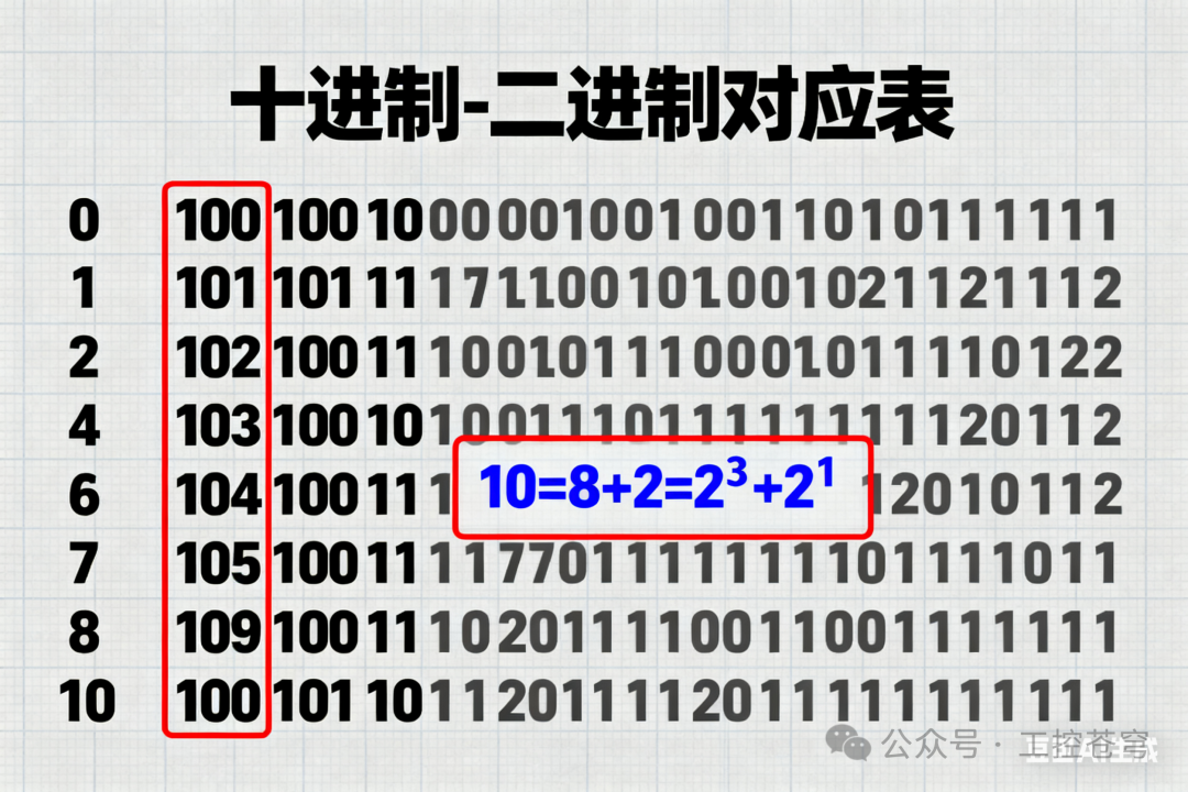
↑ “Decimal – Binary Correspondence Representation”: The left side shows decimal numbers 0-10, and the right side shows the corresponding binary numbers, with a red box highlighting “10→1010” and a note stating “10=8+2=2³+2¹”
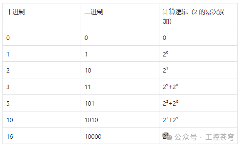
Key Conclusion:The maximum decimal number that can be represented by n bits of binary = 2ⁿ-1. For example, 4 bits of binary (1111) can represent a maximum of 15 (2⁴-1), and 8 bits of binary (11111111) can represent a maximum of 255 (2⁸-1).
2. The CPU’s “Storage Units”: Bit → Byte → Word → Double Word
The CPU does not store binary numbers randomly; instead, it packages “0/1” into “storage units” of fixed lengths, similar to how we use “boxes” to store items. Different sizes of boxes correspond to different storage units. The commonly used storage units in Siemens PLCs are divided into four levels:
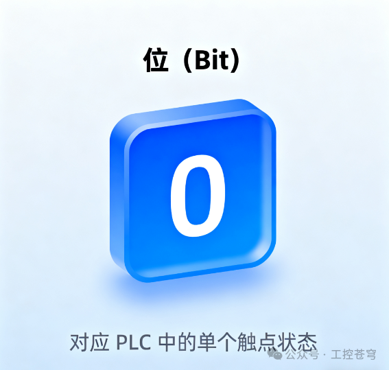
1. Minimum Unit: Bit (Bit)
- Definition: 1 “bit” can only store 1 binary number (0 or 1), which is the smallest unit stored by the CPU, corresponding to the “contact status” in the PLC (e.g., I0.0=1 indicates the button is pressed, Q0.0=0 indicates the motor is stopped).
- Representation: In the PLC, it is represented by “address + bit number”, such as I0.0 (bit 0 of byte 0 in the input module), M1.3 (bit 3 of byte 1 in the auxiliary relay).
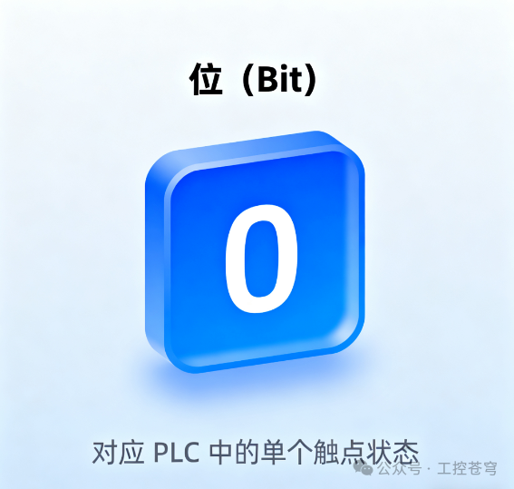
↑↑ “Bit Storage Diagram”: A blue square labeled “Bit (Bit)” contains either “0” or “1”, with a note below indicating “corresponds to a single contact status in the PLC”
2. Basic Unit: Byte (Byte)
- Definition: 1 “byte” = 8 “bits” (8 Bits), which is the most basic unit of value storage in the PLC, commonly used to store integers from “0-255” (e.g., 8-bit analog data from sensors, low 8 bits of counters).
- Maximum Value: 8 bits of binary can represent a maximum of 11111111, corresponding to decimal 255 (2⁸-1).
- Representation: In Siemens PLCs, it is represented with a “B” suffix, such as IB0 (input byte 0, containing I0.0-I0.7), QB1 (output byte 1, containing Q1.0-Q1.7).
 ↑ “Byte Storage Diagram”: 8 blue squares (bits) arranged side by side form a larger square, labeled “Byte (Byte=8 Bits)”, with a note below stating “IB0=I0.0~I0.7, range 0-255”3. Common Unit: Word (Word)
- Maximum Value: 16 bits of binary can represent a maximum of 1111111111111111, corresponding to decimal 65535 (2¹⁶-1).
- Representation: In Siemens PLCs, it is represented with a “W” suffix, such as IW64 (input word 64, containing IB64 and IB65), MW10 (auxiliary word 10, containing MB10 and MB11).
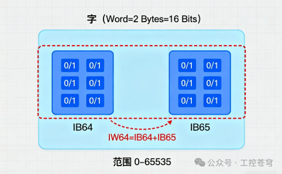
↑ “Word Storage Diagram”: 2 byte squares (total 16 bits) form a larger square, labeled “Word (Word=2 Bytes=16 Bits)”, with a red box highlighting “IW64=IB64+IB65, range 0-65535”
4. Extended Unit: Double Word (Double Word)
- Definition: 1 “double word” = 4 “bytes” = 32 “bits” (32 Bits), commonly used to store large integers from “0-4294967295”, or floating-point numbers with decimals (e.g., pressure 0.4MPa, temperature 25.5℃).
- Maximum Value: 32 bits of binary can represent a maximum of 2³²-1=4294967295.
- Representation: In Siemens PLCs, it is represented with a “DW” suffix, such as ID100 (input double word 100, containing IB100-IB103), MD20 (auxiliary double word 20, containing MB20-MB23).
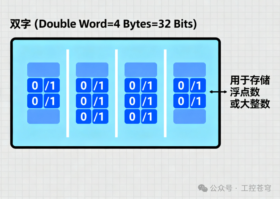
↑ “Double Word Storage Diagram”: 4 byte squares (total 32 bits) form the largest square, labeled “Double Word (Double Word=4 Bytes=32 Bits)”, with a note stating “used to store floating-point numbers or large integers”
3. Key Distinction: Unsigned vs Signed vs Floating Point
Knowing the size of the storage units, it is also important to understand the “type of values”—the way to store “positive numbers”, “negative numbers”, and “decimals” is completely different, even if they are all 16-bit “words”. This is one of the most common areas of error in PLC programming.
1. Unsigned: Only stores positive numbers
- Characteristics: All bits are used to represent “value size”, with no sign bit, allowing only storage of 0 and positive numbers.
- Applicable Scenarios: Counter values (e.g., product quantity 0-1000), raw data from sensors (e.g., photoelectric switch counts 0-65535).
- Example: The binary representation of the 16-bit unsigned number “65535” is 1111111111111111, which corresponds to the maximum decimal value.
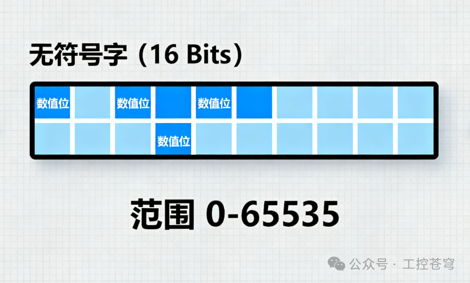
↑ “Unsigned Number Byte Diagram”: 16 bits are all labeled “Value Bits”, with a note below stating “Range 0-65535”
2. Signed: Can store both positive and negative numbers
- Characteristics: The highest bit (the leftmost bit) is the “sign bit”—0 indicates a positive number, and 1 indicates a negative number; the remaining bits represent “value size” (stored in “two’s complement” to avoid errors in positive and negative calculations).
- Applicable Scenarios: Values that need to distinguish between positive and negative, such as motor forward and reverse speeds (+1500r/min indicates forward, -1500r/min indicates reverse), temperature deviations (+5℃ indicates above the set value, -3℃ indicates below the set value).
- Example: The range of a 16-bit signed number is -32768 to +32767 (the highest bit is the sign bit, and the remaining 15 bits represent the value, 2¹⁵-1=32767).
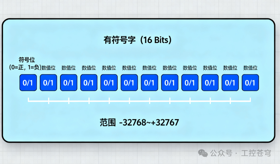
↑ “Signed Number Byte Diagram”: The first bit of the 16 bits is labeled “Sign Bit (0 = Positive, 1 = Negative)”, and the remaining 15 bits are labeled “Value Bits”, with a note below stating “Range -32768 to +32767”
3. Floating Point: Can store decimals
- Characteristics: Stored using “scientific notation” (similar to 1.23×10³), dividing the 32-bit double word into “sign bit”, “exponent bit”, and “mantissa bit”, specifically for representing values with decimals.
- Applicable Scenarios: Parameters that need to be precise to decimals, such as temperature (25.3℃), pressure (0.45MPa), flow rate (12.8m³/h).
- Note: In Siemens PLCs, floating-point numbers are represented by the “REAL” type and must exist in a 32-bit double word (e.g., MD20), and cannot exist in a 16-bit word (e.g., MW10), otherwise an error will occur.
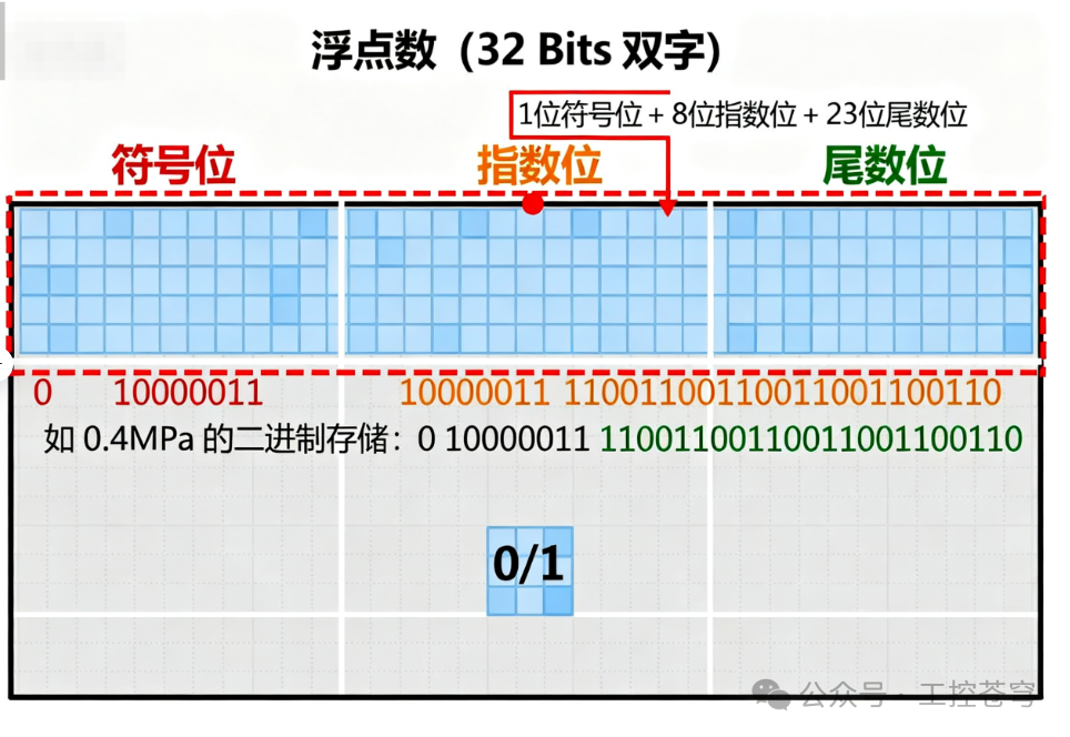
↑ “Floating Point Storage Diagram”: The 32-bit double word is divided into three parts, with a red box highlighting “1 Sign Bit + 8 Exponent Bits + 23 Mantissa Bits”, and a note stating “For example, the binary storage of 0.4MPa: 0 10000011 11001100110011001100110”
4. Practical Case: Actual Application of Data Storage in Siemens PLC
Taking the Siemens S7-1200 PLC as an example, we will look at how different data types correspond to storage in the context of a “Constant Pressure Water Supply System”:
1. Case 1: Pressure Sensor Data Storage (Floating Point)
- The pressure sensor outputs 4-20mA, corresponding to 0-1MPa, and after analog conversion, we obtain the actual pressure value of “0.4MPa”.
- Storage Choice: Floating point (REAL type), stored in 32-bit double word MD20.
- Binary Storage: The binary representation of 0.4MPa is “0 10000011 11001100110011001100110”, totaling 32 bits, corresponding to decimal 0.4.
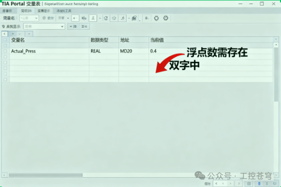
↑ “Pressure Data Storage Screenshot”: In the TIA Portal variable table, the variable name is “Actual_Press”, data type is “REAL”, address is “MD20”, current value is “0.4”, with a note stating “Floating point must exist in double word”
2. Case 2: Motor Speed Setting (Signed Number)
- The motor forward speed is set to 1500r/min, and the reverse speed is set to -1500r/min.
- Storage Choice: 16-bit signed integer (INT type), stored in 16-bit word MW10.
- Binary Storage: The binary representation of 1500 is “0000010111011100” (the highest bit 0 indicates positive), and -1500 is “1111101000100100” (the highest bit 1 indicates negative).
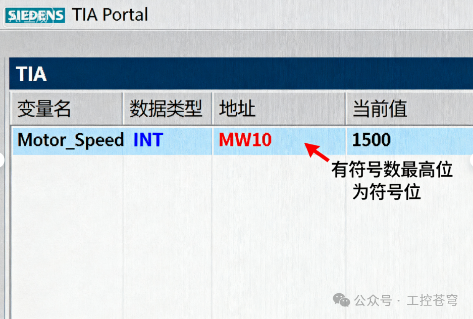
↑ “Speed Data Storage Screenshot”: In the variable table, the variable name is “Motor_Speed”, data type is “INT”, address is “MW10”, current value is “1500”, with a note stating “The highest bit of signed numbers is the sign bit”
3. Case 3: Product Counting (Unsigned Number)
- Counting products on the production line, range 0-1000.
- Storage Choice: 16-bit unsigned integer (WORD type), stored in 16-bit word MW20.
- Binary Storage: The binary representation of 1000 is “0000001111101000”, with all bits being value bits, no sign bit.
5. Pitfall Guide: 3 Common Errors in Data Storage
1. Error 1: Storing floating-point numbers in 16-bit words
- Phenomenon: TIA Portal reports “Data type mismatch”, and the program cannot be downloaded.
- Reason: Floating-point numbers require 32-bit double word storage, and 16-bit word space is insufficient.
- Solution: Change the variable address from MW10 to MD10 (double word), keeping the data type as REAL.
2. Error 2: Using unsigned numbers to store negative numbers
- Phenomenon: The program sets -50, but monitoring shows 65486 (16-bit unsigned number).
- Reason: Unsigned numbers have no sign bit, and negative numbers are calculated as “maximum value – absolute value of negative number + 1” (65535-50+1=65486).
- Solution: Change the data type from WORD (unsigned) to INT (signed).
3. Error 3: Confusing the “high and low bytes” of a word
- Phenomenon: When reading analog input IW64, the value does not match the actual value (e.g., actual 1000, displayed 40960).
- Reason: The byte order is reversed (IB64 is the high byte, IB65 is the low byte; if read as IB65+IB64, it will be incorrect).
- Solution: In Siemens PLCs, the storage of “words” is “high byte first, low byte second”, so IW64=IB64 (high 8 bits) + IB65 (low 8 bits).
6. Conclusion: Remember 3 Core Principles
- “Size Matching”: The value range determines the size of the storage unit—0-255 uses bytes, 0-65535 uses words, and 0-4294967295 or decimals use double words;
- “Type Correspondence”: Use unsigned numbers for positive values, signed numbers for both positive and negative values, and floating-point numbers for decimals to avoid type mismatches;
- “Correct Addressing”: In Siemens PLCs, a word = 2 bytes, a double word = 4 bytes, and addresses must be continuous (e.g., MW10 contains MB10+MB11, MD20 contains MB20-MB23).
Understanding the storage logic of values in the CPU not only helps avoid programming errors but also aids in understanding deeper issues such as “why analog conversion needs to be standardized” and “why floating-point arithmetic has limited precision”.
If you found this helpful, please give a thumbs up and follow! ^_^