(1) Basic Instructions
- 1. Bit Logic Instructions
- Normally Open Contact ( -||- ): This instruction detects the input signal; the button is off when not pressed and turns on when pressed. For example, in the logic controlling the machine operation with the start button, pressing the start button closes the normally open contact, and the machine starts running.
- Normally Closed Contact ( -|/- ): Normally powered, it turns off when pressed. For instance, in an emergency stop button, the circuit is normally closed, and pressing it disconnects the power to ensure equipment safety.
- Output Coil ( -() ): Completes the action output. When the logical conditions are met, the output coil is energized, driving the external device to act.
- Coil Reset ( -(R) ): Resets the coil. When the reset instruction is triggered, the coil value resets to 0.
- Coil Set ( -(S) ): Sets the coil. When the trigger condition is met, the set instruction sets a coil to 1, and when the trigger condition is no longer met, the coil value remains unchanged.
- Rising Edge Detection ( -(P) ): Directly captures the signal’s transition from 0 to 1, allowing the energy flow to connect for one scan cycle. It can be used to capture the rising edge change of a signal, such as the signal detection at the moment a motor starts.
- Falling Edge Detection ( -(N) ): Directly captures the signal’s transition from 1 to 0, allowing the energy flow to connect for one scan cycle. It is used to detect the falling edge of a signal, such as the signal change when a motor stops.
- Integer Comparison (CMP?I): Implements simple numerical comparisons. For example, comparing the sizes of two integers and executing different logical operations based on the comparison result.
- Floating Point Comparison (CMP?R): Used for more complex data flow comparisons. It is used in control logic involving floating-point numbers, such as temperature value comparisons in temperature control.
- Data Type Conversion (e.g., BCD_IBCD, etc.): Easily converts different data formats. For example, converting BCD code to an integer or converting an integer to BCD code to meet different data processing needs.
- Add/Subtract Counter (S_CUD): Performs excellently in data statistics. It can count input signals up or down, such as counting the number of products on a production line or calculating the number of times a device has operated.
- Increment Counter (S_CU): Increments the count by 1 for each counting signal received. It can be used to count the number of people entering a certain area.
- Decrement Counter (S_CD): Sets an initial value, and for each counting signal received, the count decreases by 1. For example, in inventory management, the counter decreases by 1 for each product that is shipped out.
- TON (On Delay Timer): After pressing the start button, the output signal is only activated after a set time. This is suitable for avoiding sudden device starts, such as setting a delay time for a motor to start after the start button is pressed for a certain period.
- TOF (Off Delay Timer): After pressing stop, the power is cut off after a while. For example, delaying the light off after the fan stops, allowing the fan to remain powered for a period after stopping.
- TP (Pulse Generation Instruction): Sets the output Q to be active for a preset time PT. When IN changes from 0 to 1, the timer starts, Q immediately outputs 1, beginning the pulse output. After the timer starts, ET continuously increases from 0ms, and when it reaches the preset time PT, Q changes to 0 state.
- ADD (Addition): Performs numerical addition. For example, adding the values collected by two sensors to calculate the total.
- SUB (Subtraction): Performs numerical subtraction. Used in logic for calculating differences, such as calculating the difference between two temperature values.
- MUL (Multiplication): Performs numerical multiplication. It can be used to calculate areas, volumes, and other scenarios requiring multiplication.
- DIV (Division): Performs numerical division. For example, division is needed when calculating averages.
- SHR (Right Shift Instruction): Shifts the binary bits of a word or double word to the right by a specified number of bits. It can be used for data processing and conversion, such as right-shifting binary data by one bit is equivalent to dividing by 2.
- SHL (Left Shift Instruction): Shifts the binary bits of a word or double word to the left by a specified number of bits. Left-shifting by one bit is equivalent to multiplying by 2.
- ROR (Rotate Right Instruction): Rotates the bit values of the input to the right, with the position rotated by count N, and then loads the result into the storage unit assigned to OUT.
- ROL (Rotate Left Instruction): Rotates the bit values of the input to the left, with the position rotated by count N, and then loads the result into the storage unit assigned to OUT.
(2) Siemens PLC Instructions
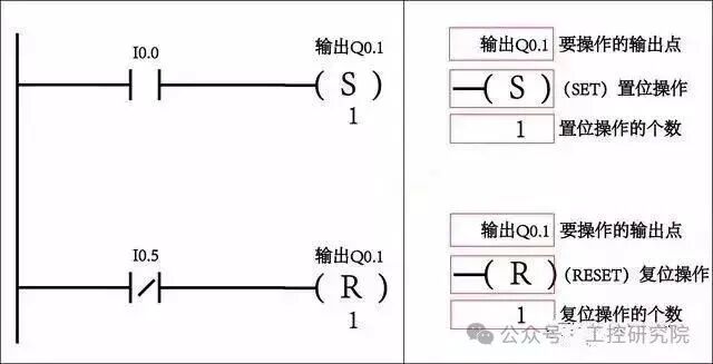 This image shows an example of PLC ladder diagram programming. Top left: When I0.0 is activated, output Q0.1 is set; bottom left: When I0.5 is activated, output Q0.1 is reset. The right side provides annotations for the set and reset operations, including the output points to be operated, the type of operation, and the number of operations.
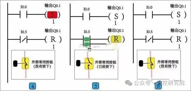 This image displays three sets of PLC ladder diagram control logic and an external normally closed button state diagram. The left ladder diagram connects the normally open contact I0.0 to the set instruction for output Q0.1, while the normally closed contact I0.5 connects to the reset instruction for output Q0.1; the middle ladder diagram is similar, with I0.0 normally open and I0.5 normally closed controlling the set and reset of Q0.1, with color annotations; the right ladder diagram also has I0.0 controlling the set of Q0.1 and I0.5 controlling the reset. Below is an external normally closed button state diagram, showing the states of not pressed, pressed, and not pressed.
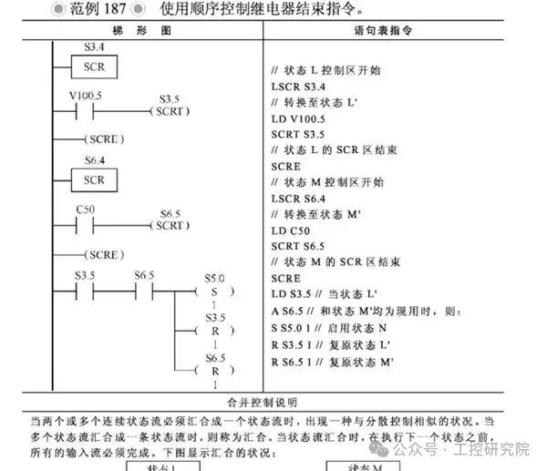 This image shows example 187 using the sequential control relay end instruction. It includes ladder diagrams and statement table instructions, with nodes such as S3.4, S3.5, and related connections in the ladder diagram, and the statement table instructions provide detailed explanations of state transitions and other operations, with a control merging explanation below.
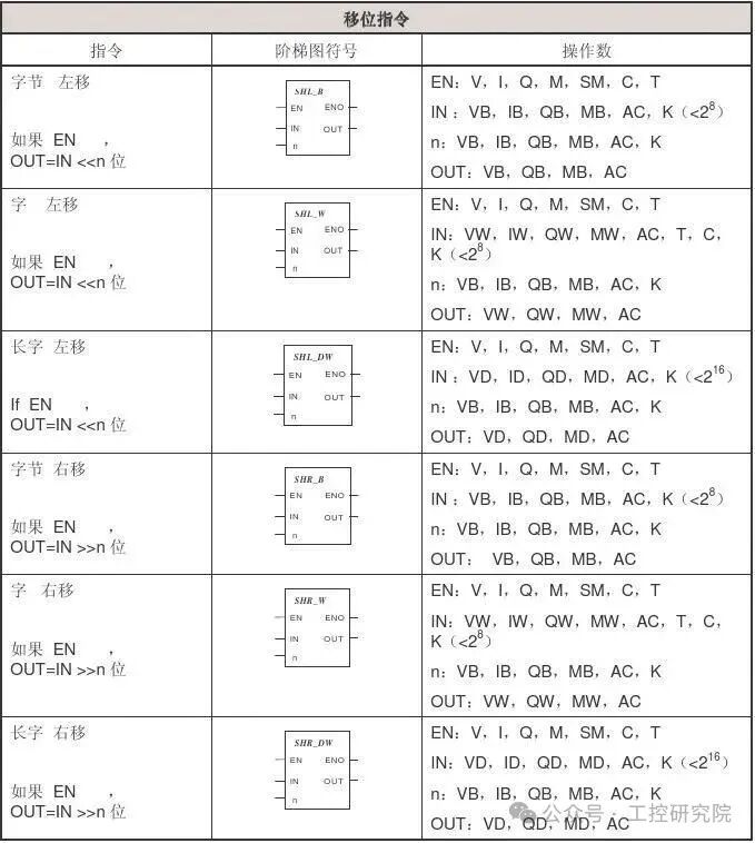 This is a diagram of the shift instruction table, containing three columns: instruction, ladder diagram symbol, and operand. The instructions include byte left shift, word left shift, long word left shift, byte right shift, word right shift, and long word right shift; each instruction corresponds to a ladder diagram symbol showing ports like EN, ENO, etc.; the operand column lists the value ranges for EN, IN, n, OUT, etc.
If this is helpful, please like, follow, and share!!