In the field of industrial automation, the PLC (Programmable Logic Controller) is known as the “smart brain” of the equipment, controlling the orderly operation of the entire production process. However, when the indicator light on the PLC panel suddenly lights up, it often indicates that the system has encountered a problem, causing many engineers to feel troubled. Don’t worry, today we present a super practical guide for handling PLC indicator lights across 10 common brands, helping you quickly troubleshoot faults and restore normal operation of the equipment!
Siemens
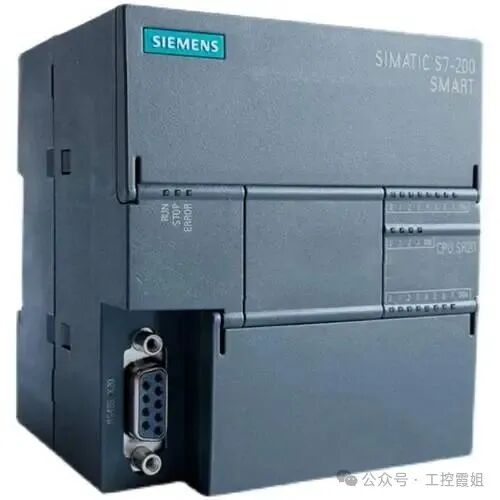

Siemens PLCs are widely used in industrial scenarios, and their indicator light status can accurately reflect the equipment condition.
- SF (System Fault) light is on:This indicates that a system fault has occurred, possibly due to internal addressing errors, programming address area exceeding limits, module damage, or loose plugs. When handling this, first try to clear the program in the PLC. If the SF light remains on, it is likely a hardware fault; if the light goes out, it may be a program issue. At this point, you can check the information on the S7-300 PLC online. If the SF light is on and the BF (Communication Fault) light is flashing, it is likely related to the distributed fieldbus PROFIBUS-DP communication or DP slave. You need to check whether the hardware configuration matches the actual hardware, whether the DP slave address is set correctly, and whether the PROFIBUS cable and communication connectors are properly connected.
- RUN (Run) light is off:Check whether the mode switch is in the RUN position. If it is in the RUN position but the light is still off, it may be that the program has not started. Further investigation is needed to check whether there are errors in the program, such as infinite loops, memory overflow, etc. Also, check whether there are hardware faults interfering with program execution, such as CPU module overheating or internal chip damage.
- PWR (Power) light is flashing:Use a voltmeter to measure the input voltage to confirm whether it is within the range of 20-28V. If the voltage fluctuates, check whether the power wiring is loose and investigate whether there are contact issues. If necessary, consider replacing the power module.
Mitsubishi
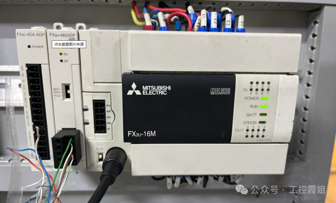
Mitsubishi PLCs are favored by engineers for their high reliability, and their indicator lights are also key clues for troubleshooting.
- BATT (Battery Level) light is on:When the red LED lights up, it means that the lithium battery in the PLC is nearing the end of its life (about one month remaining), and it needs to be replaced quickly to prevent the program in the PLC from disappearing automatically. If the LED remains lit after replacing the battery, there may be a problem with the CPU board, and you need to contact Mitsubishi after-sales service.
- ERROR (Error) light is on:If conductive foreign objects enter the PLC or if it is affected by external abnormal noise, causing the CPU to lose control or the computation cycle to exceed 200ms, a WDT error will occur. At this time, all outputs of the PLC will turn OFF. You can try a breakpoint reset and check whether the PLC grounding meets the requirements.
- ERROR light is flashing:When the red LED is flashing, it may indicate unreasonable program loops, incorrect parameter settings, or interference. It may also be due to forgetting to set timer or counter constants. You can use the handheld writer FX-20P-E to check D8004, and then check D8060~D8069 based on the content of D8004 to see if there is any interference.
- POWER (Power) light is off:When the host is powered on, the green LED should light up. If the indicator light is off, you need to confirm the power wiring situation, check for poor contact, load short circuits, or overcurrent situations. If the indicator light is faulty after connecting the power, you can disconnect the 24+ terminal wiring. If the indicator light is normal, it indicates that the PLC’s DC load is too large, and you need to use another DC 24V power supply. If the indicator light is still off after disconnecting the wiring, the internal fuse of the PLC may have blown, and you need to replace the fuse and check the cause.
Omron

Omron PLCs occupy an important position in industrial automation due to their stable performance, and the interpretation of their indicator light status is as follows.
- ERR (Error) light is constantly on:After powering on, if the POWER light is on, the ERR light is constantly on, and the digital display shows no alarms, this fault may be caused by electromagnetic interference, noise interference, static electricity, etc., leading to damage to the CPU circuit MPU, ASIC, or memory chip. In daily use, attention should be paid to anti-interference measures, such as using shielded cables for communication and signal lines, separating them from high-current power cables, isolating the PLC from high-power or high-frequency devices, and adding isolation transformers at the AC220V power input end, ensuring that the DC24V power supply does not share ground with high-power equipment power supply.
- RUN light is flashing:For CP1 series PLCs, if the POWER light is on after power-up, the RUN light is flashing, and the PLC cannot operate normally, it may be that the PLC is affected by external signal interference or signal shock during operation, causing the system signal on the CPU board to be lost or the EEPROM chip storing system information to be damaged. Similarly, anti-interference measures should be taken to avoid similar problems from occurring again.
Schneider
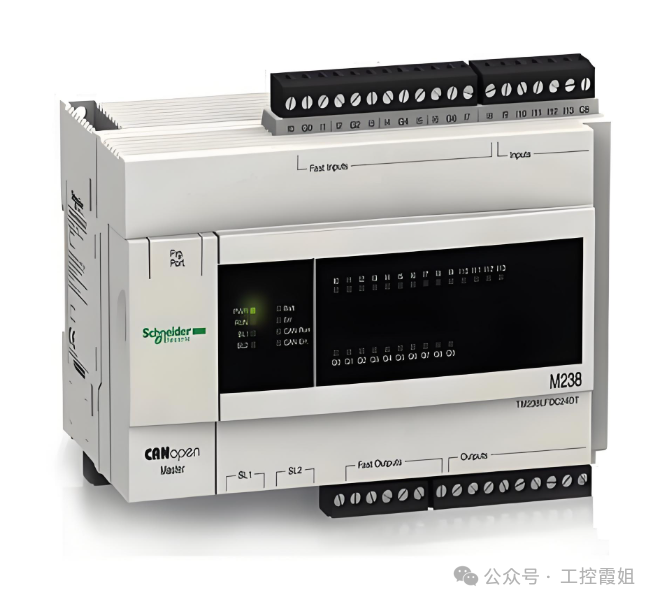
Schneider PLCs are widely used in the field of industrial automation, and their indicator lights can intuitively reflect the operating status of the equipment.
- I/O module indicator light is red:This indicates that there is a fault or abnormality in the corresponding input or output module, which may be due to unstable power supply, incorrect wiring connections, module faults, etc. When troubleshooting, first check the power supply issue, see if the power supply wiring is loose or damaged, and consider adding a stable power filter or increasing a backup power supply if necessary. Next, check the module connections and wiring to ensure that the module is correctly connected to the PLC backplane, check cable connections and input/output signal line connections to avoid electromagnetic interference. If the red light remains on after eliminating the above issues, it may be a fault in the module itself. You can refer to the fault code table to understand the specific meaning of the flashing light and take corresponding repair measures, or restart the module or the entire PLC system. If the problem persists, the faulty module needs to be replaced.
- ERR indicator light is on:Check whether the power supply is normal, including whether the power supply line connections are secure and whether the power outlet is powered; check whether the input signals are correct, such as whether sensors, buttons, etc., are working properly; check whether the output signals are normal, ensuring that all output devices are functioning properly; check for errors in the program, especially logical errors or address errors; if all the above steps are normal, there may be a problem with a certain module of the PLC that needs to be replaced or repaired.
ABB
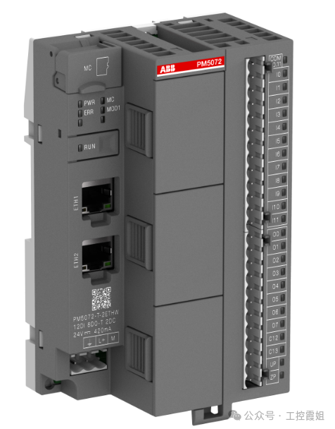
ABB PLCs perform excellently in industrial control, and their indicator light status is an important basis for judging faults.
- Power indicator light is flashing:This indicates that the power supply voltage is unstable or below the normal range, which may cause the device to fail to start, abnormal program operation, communication faults, etc. When handling this, use a voltmeter to measure the power supply voltage of the PLC, ensuring it is within the normal working range. If the voltage is unstable or below the normal range, check the grid voltage or power supply line; carefully check the power supply line connections to ensure there are no aging, poor contact, or short circuit issues. If you suspect a power module fault, try replacing it with a new power module for testing. If the PLC is connected to an excessive load, try reducing the load or increasing the power module’s power supply capacity. In cases of significant fluctuations in grid voltage, consider adding a voltage stabilizer or UPS at the PLC power input end to ensure stable power supply voltage.
- Error indicator light is on:This may be caused by power issues, input/output faults, hardware faults, memory chip faults, communication module faults, CPU module faults, software faults, or external interference preventing the PLC from starting. Follow these steps for troubleshooting: First, check the power supply, using a voltmeter to test the PLC power supply voltage, ensuring it is within the rated voltage range. Check the power supply line for stability, looking for open circuits or short circuits, and check whether the internal fuse of the PLC is damaged and whether the power line has good contact. Next, perform a visual inspection of the PLC for any obvious physical damage or burn marks, and check whether all connectors and plugs are securely connected without looseness or disconnection. Then, check the I/O modules to see if the input module is receiving the correct signals and whether the output module has any fault indicator lights on. Next, check the memory; if the PLC program is lost or damaged, use a backup program to restore it and check the memory chip for faults with specialized tools. Then, check the software and program, using PLC programming software to open and check the program for syntax errors, logical errors, or data loss. If there are errors, correct them and recompile. Finally, check the communication to ensure that the communication connection between the PLC and other devices is normal. If there are communication faults, repair the communication lines or reconfigure the communication parameters.
Rockwell (Allen-Bradley)
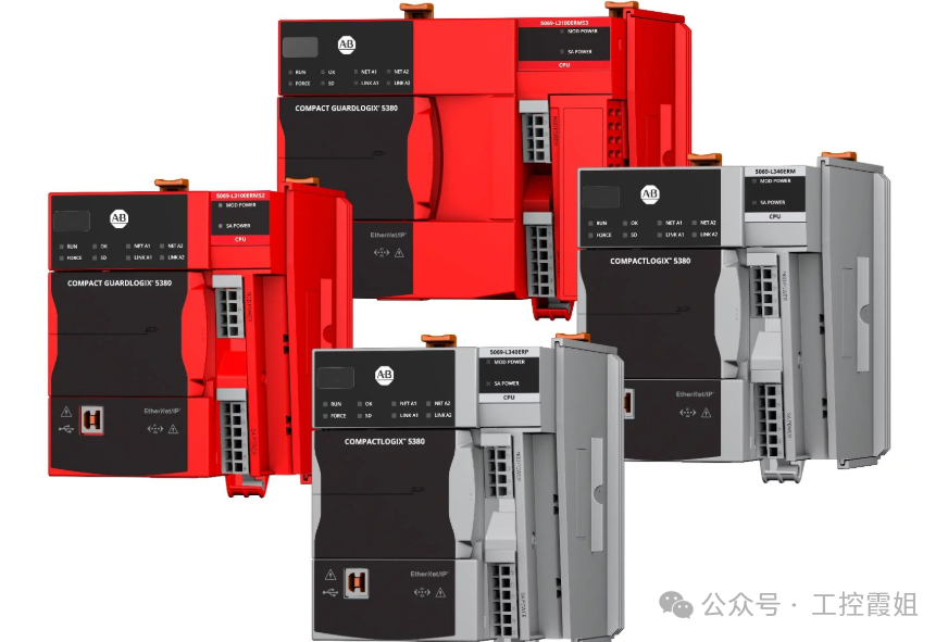
Rockwell PLCs are widely used in automation systems, and their indicator lights have unique fault indication functions.
- I/O indicator light is abnormal:The I/O indicator lights of Rockwell PLCs are subdivided for each input and output point, directly displaying the signal status of the corresponding channel. When the field device signal is not properly connected or the output execution element fails, the corresponding I/O point indicator light will provide feedback. If an input point indicator light does not light up as expected, check whether the corresponding sensor, switch, etc., is working properly and whether the connection line is loose or broken. If the output point indicator light is on but the execution element does not act, check whether the execution element is damaged, whether there are short circuits or open circuits in the output line, and check whether the logical control of that output point in the PLC program is correct.
- Fault indicator light is on:If the fault indicator light is on, a comprehensive judgment is needed. First, check the status of other related indicator lights, such as whether the power indicator light is normal. If the power indicator light is normal, it may be a hardware fault, such as module damage or internal wiring connection issues. If accompanied by abnormal communication indicator lights, there may be communication faults, and you need to check the communication cable connections and communication parameter settings. At the same time, use Rockwell’s programming software for online diagnostics to read detailed fault information and perform targeted troubleshooting and repairs based on the fault codes and prompts.
Panasonic
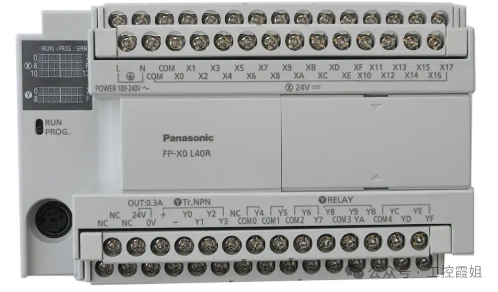
Panasonic PLCs occupy a place in the field of industrial automation with their advanced technology and reliable performance. The interpretation of their indicator light status is as follows.
- POWER light is off:If it is off, please confirm whether the power wiring is correct and secure. If the same power supply also drives sensors and other devices, check for load short circuits or overcurrent situations. If none of the above reasons apply, it may be that conductive foreign objects or other abnormal situations have caused the fuse in the basic unit to blow (some products cannot replace the fuse themselves). At this time, you can first try to check external loads and wiring issues. If the problem cannot be resolved, contact professional maintenance personnel to check the internal situation of the PLC.
- ERR light is flashing:When there are program calculation errors (such as division by zero, incorrect parameter settings, etc.), or when there are abnormal interferences or conductive foreign objects causing changes in program memory content, this light will flash, and the PLC will be in STOP state, with all outputs turning OFF. You can check error prompts and error codes online through programming software, check whether there are errors in the program, and investigate whether conductive foreign objects have entered and high-intensity interference sources exist. When a calculation error (error code 45) occurs, the address where the error occurred will be saved in a special data register, which can be used to locate the error. Error codes 1-9 indicate program syntax errors, and after locating the erroneous statement, correct it and clear the error. Error codes above 20 indicate self-diagnostic errors other than syntax errors, which can be cleared directly using programming software. If errors still frequently occur after clearing, further inspection of hardware and program operating environment is needed to eliminate potential interference factors.
Delta
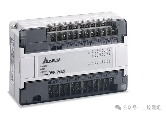
Delta PLCs are popular among many users in the industrial control market due to their high cost performance, and their indicator light status can help quickly locate faults.
- PWR light is off:Check whether the input voltage of the power supply is within the rated range, confirm whether the power plug and socket connection is tight, and whether the power line has damage or open circuit issues. If the external power supply is normal, it may be a fault in the internal power module of the PLC. You can open the PLC case (when powered off and ensuring safety) to observe whether there are obvious component damages or burn marks on the power module. If component damage is found, you need to replace the power module with the same specifications; if you cannot determine the fault point, it is recommended to contact Delta’s after-sales technical support for professional testing and repair.
- ERR light is on:This may be caused by program errors, hardware faults, or communication anomalies. First, check the program syntax and logic online using programming software to see if there are any undefined variables or incorrect instruction usage. If the program is fine, check the hardware connections, including whether the wiring connections between the I/O modules and the CPU module are loose, and whether the installation of expansion modules is in place. If communication functions are involved, check whether the communication cable connections are normal and whether the communication parameter settings match the connected devices. For complex faults, you can use Delta’s diagnostic tools or refer to the troubleshooting process in the product manual for in-depth analysis.
XC
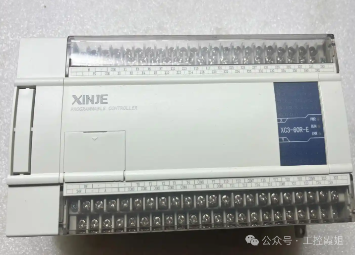
XC PLCs are widely used in small automation control systems, and their indicator lights can intuitively reflect the operating status of the equipment.
- RUN light is off:Check whether the working mode selection switch of the PLC is set to the RUN position. If it is already in the RUN position, check whether the program has been correctly downloaded to the PLC. You can check the program download status and related error prompts through programming software. At the same time, check the hardware connections of the PLC, such as power connections, I/O wiring, etc., to see if there are any looseness or short circuit issues. If both hardware and program are fine, it may be that the CPU module of the PLC or related control circuits have failed, and you need to contact XC after-sales for further testing and repair.
- ERR light is flashing:This usually indicates that there is an error in the program or an abnormal situation during the operation of the device. Use programming software for online monitoring to check error codes and detailed error information. Common errors include syntax errors, logical errors, data overflow, etc. Based on the error prompts, carefully check whether the program is written correctly, whether the logical control is reasonable, and modify and debug the problematic program segments. If the error is related to hardware, such as abnormal input/output point status, check the wiring of the corresponding I/O points and whether external devices are working properly, and investigate whether there is interference causing signal anomalies. After resolving the issue, you can clear the error state through programming software and re-run the PLC to see if it returns to normal.
Fatek
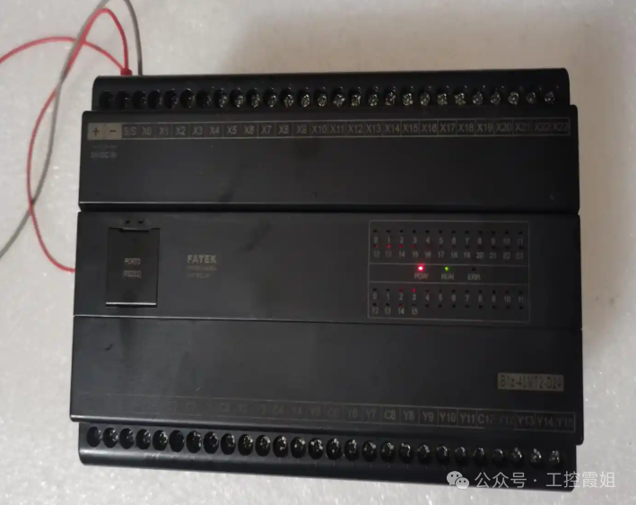
Fatek PLCs are applied in industrial automation due to their flexible programming and stable performance, and their indicator light status can be used for fault judgment.
- POWER light is abnormal:If the POWER light is off, check whether the power input is normal, including whether the output voltage of the power adapter meets the PLC requirements and whether the power plug is well connected to the PLC power interface. If the power input is normal but the light is off, it may be a fault in the internal power circuit of the PLC. You can try replacing the power adapter for testing. If the POWER light is flashing, it may indicate unstable power voltage or a short circuit in the PLC. At this time, you need to use a multimeter or other tools to detect the power voltage fluctuation and check whether there are signs of short circuits in the internal circuit of the PLC, such as burnt components or short circuits. For internal circuit faults, it is recommended that professional maintenance personnel carry out repairs to avoid further damage caused by self-disassembly.
- ERR light is on:The ERR light indicates that the PLC has encountered a fault, which may involve multiple aspects of hardware and software. First, read the error code through programming software to determine the type of fault. If it is a software fault, such as a program error, check the program syntax and logic for issues such as infinite loops or uninitialized variables, and modify and optimize the program. If you suspect a hardware fault, check whether the I/O module connections to the host are loose and whether there are signs of damage to electronic components on the module, such as bulging capacitors or abnormal heating of chips. For hardware faults, if it is determined that a certain module is damaged, you can replace it with a module of the same model for testing to restore normal operation of the equipment.
Understanding the meanings and handling methods of the indicator light statuses of various brands of PLCs is like having a key to unlock the door to equipment fault diagnosis. We hope this guide can become a valuable assistant in your daily work, making PLC fault troubleshooting easier and more efficient, ensuring the stable operation of industrial production. If you encounter special indicator light anomalies during actual operation, feel free to leave a comment to share, and let’s discuss solutions together!