
This article shares examples related to SiemensS7-300PLC analog values, covering the following key points:
1. Obtain values fromtransmittersand control them
2. Call the analog function block FC105
3. Set up the AI module
4. Select the AI range block
This example involves debugging a flow regulation loop, where the flow transmitter outputs a 4-20 mA DC signal to the SM331 analog input module. The module converts this signal into a floating-point number, and then the program calls FC105 to convert this value into engineering units, allowing us to monitor the actual flow value in the project.
The analog input AI uses the SM311 module, which is 8x12Bit (8 channels, 12 bits) with the product number 6ES7 331-7KF02-OABO. In the analog conversion, it utilizes the values extracted from the sensors or transmitters, converting the voltage or current at the AI module, and then sends the values to Siemens’ CPU for processing, thereby detecting and controlling the sensor values, as shown in the figure:

Analog Input Module
Analog inputs are used to connect voltage and current sensors, thermocouples, resistors, andthermistors, to achieve the connection between PLC and analog process signals.
The analog input module converts the analog signals sent from the process into digital signals for internal processing by the PLC.
The SM311 input module used in this project is shown in the figure below. This module has the following characteristics:
The resolution is from 9 to 15 bits + sign bit (for different conversion times), and different measurement ranges can be set.
The range module can mechanically adjust the basic measurement range of current/voltage.
The STEP 7 hardware configuration tool can be used for fine-tuning. The module sends diagnostic and over-limit interrupts tothe programmable controller‘s CPU.
The module sends detailed diagnostic information to the CPU.
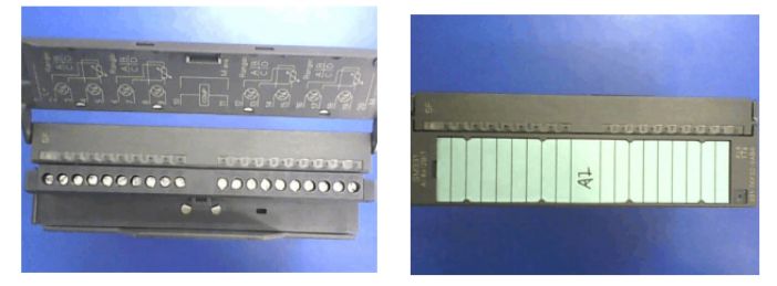
Wiring Method of the Analog Input Module
Two-wire and four-wire current systems only have two signal wires. The main difference between them is: the two-wire current system’s two signal wires provide power to the sensor or transmitter and also provide the current signal; while the four-wire current system’s two signal wires only provide the current signal.
Therefore, sensors or transmitters that provide two-wire current signals are typically passive; while those providing four-wire current signals are active.
When the PLC’s input channel is set to connect to a four-wire sensor, the PLC only collects the analog signal from the terminals of the input channel, as shown in Figure 2-3. When the PLC’s input channel is set to connect to a two-wire sensor, as shown in Figure 2-2, the PLC’s analog input channel must also output a 24V DC power supply to drivethe two-wire sensor.
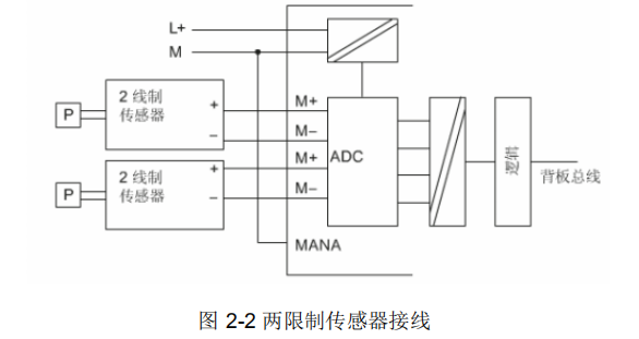
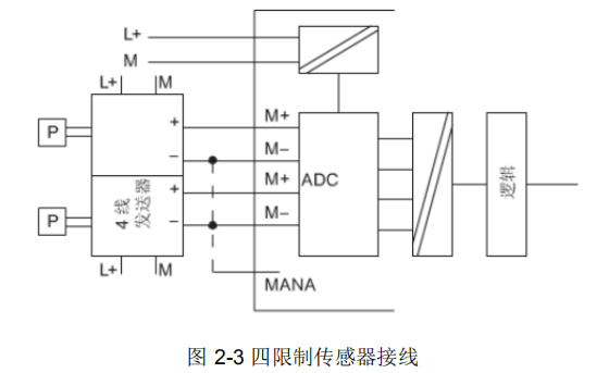
Sensor Models
◆ Two-wire (requires a 24V DC power supply, output signal is 4-20 mA current), i.e., + connects to 24V DC, negative outputs 4-20 mA current.
◆ Four-wire (has its own power supply, generally 220VAC, output signal line + is 4-20 mA positive, – is 4-20 mA negative.
01. (Taking 2 positive, 3 negative as an example), in two-wire mode, the positive 2 outputs 24V DC voltage, and 3 receives current, so when encountering a two-wire sensor, one connection method is to connect 2 to the sensor positive, and 3 to the sensor negative; the jumper is for the two-wire current signal. The second connection method is to leave 2 floating and connect 3 to the sensor negative while the sensor positive must connect to the cabinet’s 24V DC; the jumper is for the two-wire current signal.
02. (Taking 2 positive, 3 negative as an example), in four-wire mode, positive 2 receives current, and 3 is negative. (The advantage of four-wire is that the negative signal of the sensor will not significantly affect accuracy when the cabinet’s M is at a different level since it is the current loop of the sensor itself.) When encountering a four-wire sensor, one method is to connect 2 to the sensor positive, 3 to the sensor negative, and the PLC jumper is for four-wire current.
“Connect the sensor positive to PLC’s 3, leave 2 floating, and the jumper is for two-wire current.” This method applies to both four-wire and two-wire sensors, and everyone can try it; the good methods will be recognized.
03. (Taking 2 positive, 3 negative as an example), the connection method for a four-wire sensor with the PLC in two-wire mode: connect the negative signal line to the cabinet’s M line. Connect the sensor positive to PLC’s 3, leave 2 floating, and the jumper is for two-wire current.
04. (Taking 2 positive, 3 negative as an example), voltage signal: connect 2 to sensor positive, 3 to sensor negative, and the PLC jumper is for voltage signal.
Range Card Settings
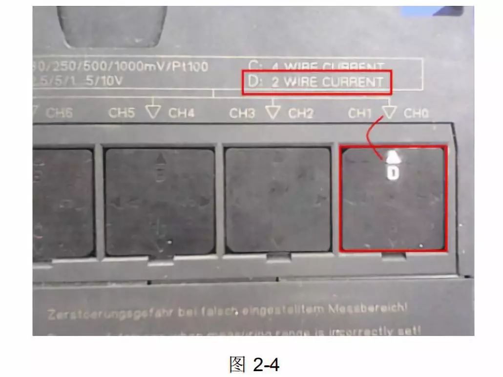
The range card is mounted on the left side of the template, and the allowed settings are “A”, “B”, “C”, and “D”, which are suitable for different types and ranges of measurements. It must be correctly set before installing the template.
Analog templates without range cards have different terminals for adapting to voltage and current measurements, so the measurement type can be set by correctly connecting the relevant terminals.
A brief description of setting different measurement types and ranges is printed on the template. For this project, the water level measurement uses a two-wire transmitter, so “D” is selected, as shown in Figure 2-4.
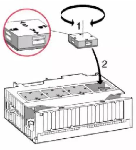
Input Module Settings
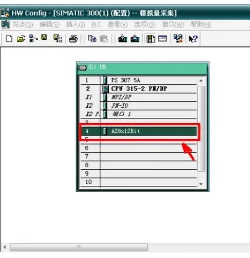
After setting up the rack in the “Hardware” interface, double-click the input module “ATBx12bit”, as shown in the figure:
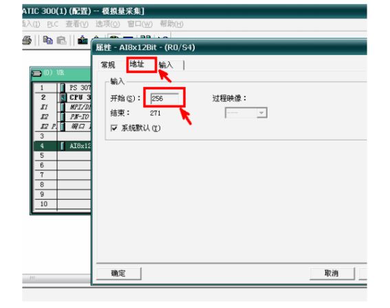
After double-clicking the input module, an execution box will pop up. Click on “Address” and change the starting address to “256”, as shown in the figure:
After changing the address, click on “Input” and set the “Measurement Type” to “2DMU” for the sensor type. (This time a two-wire transmitter is used).
AI System
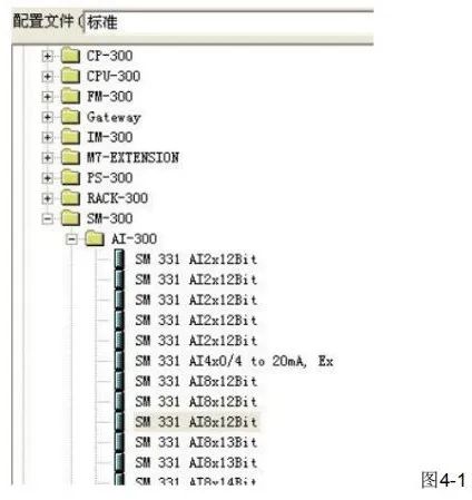
Establish a Siemens hardware module after adding the power supply and CPU, and select the AI module in the configuration file, as shown in Figure 4-1.
When completed, this module will appear in the hardware system, as shown in Figure 4-2.
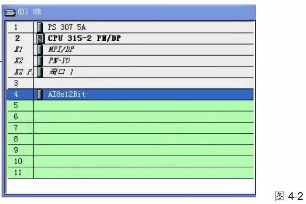
After this operation is successful, double-click to select, and click on the input dialog box, as shown in Figure 4-3.
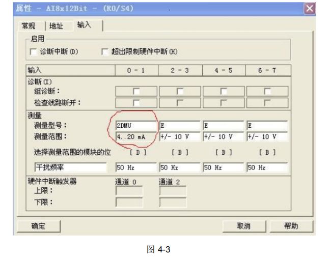
After selection, click OK, and then proceed to program writing.
AI Program
In the S7-300, the AI module’s program has already been written by the manufacturer; just call the function module as shown in Figure 4-4.
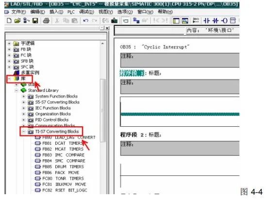
In the dialog box below Figure 4-4, find the FC105 function block, as shown in Figure 4-5.
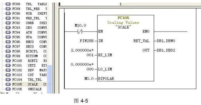
IN: Enable terminal.
HI_LIM: High limit.
L0_LIM: Low limit.
BIPOLAR: Polarity.
RET_VAL: Error storage.
OUT: Output value (liquid level)
Source: Network, copyright belongs to the original author. If there are copyright issues, please contact us in time to delete. Thank you!
Free robot learning materials available ↓
Click “Read Original” to sign up for robot courses
Give a “Look” if you find it useful