Previously, we introduced the common layout methods of industrial robots and robot control cabinets in welding equipment. Today, we will discuss the selection of industrial robots for welding. Regardless of the brand of the robot, the selection is based on actual applications and process layouts. This article uses the mainstream robot brand FANUC in the welding industry as an example to briefly introduce the selection of welding robots.
1. Related Terminology
1.1 Robot Load Calculation and Overload Solutions
The maximum mass that a robot can bear in any posture within its allowable working range. The robot load depends not only on the mass of the load but also on the speed and direction of the robot’s movement.
1.2 Degrees of Freedom (Axis Count)
The number of axes configured in the robot directly affects its degrees of freedom. If the robot arm requires a high degree of freedom for operation, a multi-axis robot must be selected to meet multi-angle movement requirements. Welding workshops generally use 6-axis robots, with a small number of 4-axis robots.
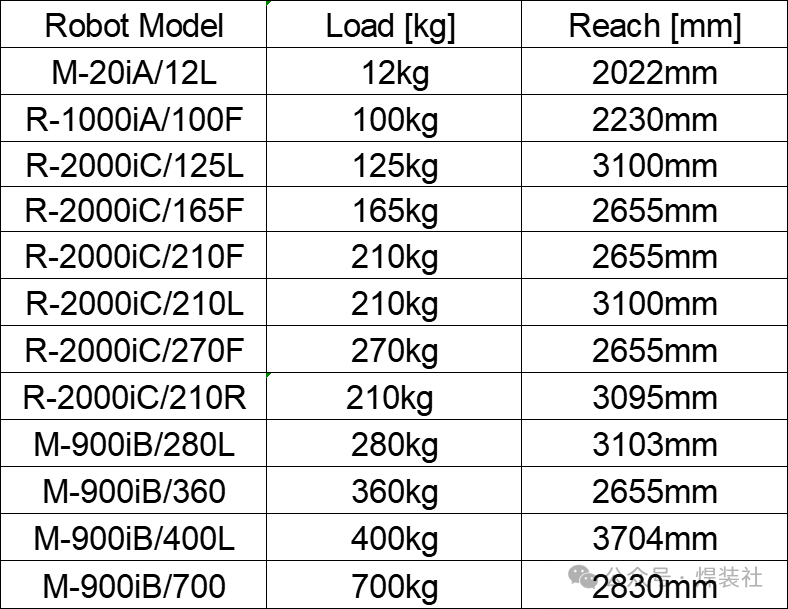
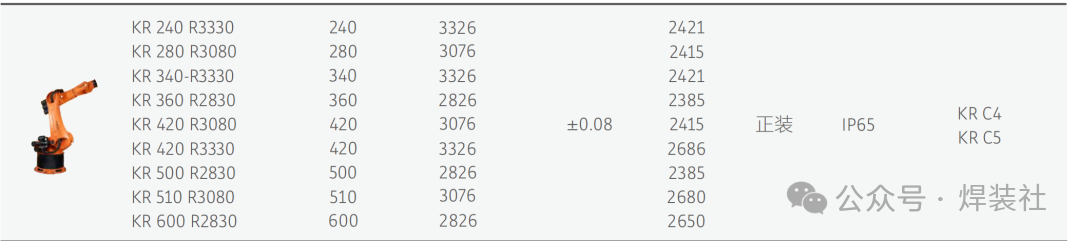
1.3 Maximum Motion Range
The maximum distance that the robot can reach during operation. Different models of robots have different working radii, which need to be analyzed in conjunction with the robot’s effective load to confirm the appropriate model. Some load and power ranges of FANUC brand robots are as follows.
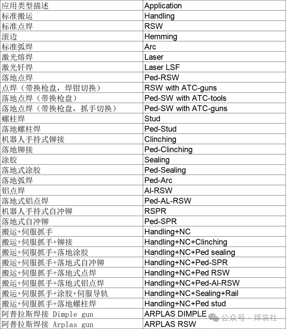
2. Robot Applications
The first step in robot selection is to confirm its application. The most common applications in welding workshops are spot welding (RSW) and handling. The common robot applications in welding workshops are shown in the table below.
3.
Installation Methods
The installation method depends on the robot application and process layout. Robot installation methods include ground, overhead, inclined angle, high platform, side wall, and wall-mounted. The most commonly used installation method is ground installation. The overhead, wall-mounted, and inclined angle installation methods limit the robot’s range of motion, so accessibility should be carefully verified in simulation software during selection.
4. Robot Models
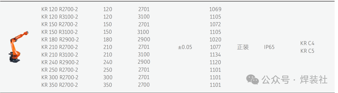
When selecting a specific robot model, it is usually best to choose the most commonly used robots. Common robot brands generally have stock, and the prices are relatively moderate. After confirming the robot model, it is necessary to calculate the robot’s load and verify its accessibility through simulation. The commonly used robot models in welding workshops from FANUC are as follows.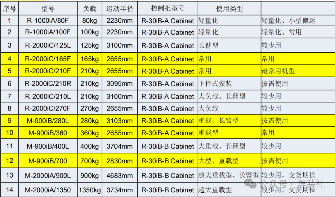 KUKA’s commonly used series includes high-load robots ranging from 90-300KG.
5. Cable Length Design Points and Techniques for Welding Project Layout
5.1 Control Cabinet Cable (RCC) Length
The length of the RCC cable depends on the relative position of the control cabinet and the robot, as well as the layout of the cable tray. RCC cables are generally available in series, and the corresponding length can be selected as needed. Common lengths for FANUC robot RCC cables are 7m, 14m, 20m, 30m, 7m+7m Flex, 7m+14m Flex, 7m+20m Flex, 14m+7m Flex, and 14m+14m Flex. When determining the RCC cable length, special attention should be paid to the robot’s installation position. When installed on a standard base, the height of the base must be processed. When installed on a walking axis, the length of the flexible cable in the drag chain must be considered. When the robot is installed in a pit or on a steel platform, the depth of the pit and the height of the steel platform must be accounted for in the cable length.
5.2 Teach Pendant Cable (TP) Length
The length is directly related to the distance between the robot and the control cabinet, with a certain length of excess processed as needed. Common lengths for FANUC robot TP cables are 10m and 20m.
6. If the robot is used for welding point applications (gun spot welding and drop point welding), a welding gun motor should be configured, which is usually provided by the robot manufacturer and integrated by the welding gun manufacturer. If it is drop point welding, attention should also be paid to the length of the fixed welding ground cable, which is commonly 7m, 14m, 20m, or 30m for FANUC robots. If the welding gun motor is not from the FANUC brand, an encoder must be configured, which is usually provided by the motor supplier.
7. DCS Function. The DCS function can set the working range and stop distance for the robot’s operating area. When the robot’s tool or body leaves the safety area, the robot’s motor power is turned off, stopping movement. This can effectively save floor space while ensuring the robot’s safety area is protected, preventing collisions between the robot’s tools, body, and surrounding equipment. The area where robots and humans interact requires the DCS function, which is enabled and set by the teaching personnel during teaching.
8. Communication Methods with PLC. The communication methods between industrial robots and PLCs mainly include Ethernet communication, fieldbus communication, serial communication, I/O module connections, and wireless communication. Among these, Ethernet communication (such as Profinet, Ethernet/IP) and fieldbus (such as Profibus DP, CC-Link) have become mainstream solutions in industrial automation due to their high speed, stability, and real-time capabilities, suitable for complex scenarios such as automotive manufacturing and production line collaboration. Specific projects need to be confirmed with the client.
9. Quick Change Function. If the robot tool requires quick change, the quick change function needs to be configured.
10. Servo Rail Motor. When the robot is installed on a walking axis, a servo rail motor needs to be configured. Light to medium load robots typically have one servo rail motor, while heavy load robots have two, such as the FANUC M-1000iA robot. The number of servo rail motors needs to be confirmed with the manufacturer during selection.
11. If the robot works in conjunction with a turntable, the turntable motor is provided by the robot manufacturer, and a cable for the turntable motor to the robot control cabinet needs to be configured, with the length confirmed in the layout diagram.
12. If the robot tool is an NC gripper, the motor for the NC axis is provided by the robot manufacturer, and the motor model needs to be confirmed with the manufacturer.
13. Other configurations, such as ZDT software, pipeline packages, etc., can be selected based on the configuration and needs of the main engine manufacturer.

Disclaimer: Unless otherwise specified, all images are sourced from the internet or user submissions, and the copyright belongs to the original author or source. We are committed to protecting the copyright of the original author. If there are any copyright issues, please contact us for resolution.
Previous Highlights
Common Layout Methods for Robot Control Cabinets
Industrial Robots for Welding Equipment
Common Pitfalls in Procurement Selection for Welding Design NO.1
Comparison of Common Detection Styles and Switch Models in Welding Design
Key Points and Techniques for Designing Layout Diagrams for Welding Projects