Click to follow and never lose your way in learning!
Last time, we ventured into the mysterious world of the MODBUS protocol and conducted a preliminary exploration of this “big player” in industrial communication. I wonder if you are still immersed in that wonderful learning atmosphere? If your knowledge isn’t solid, make sure to review it quickly so you don’t fall behind!
Today, we will continue to dig deeper and extract the core elements of the MODBUS protocol to fully understand them. This way, we can navigate the realm of industrial automation more steadily and further. Let’s not waste time and dive into the ocean of knowledge to start today’s exploration!
1
Master-Slave Architecture: The “Brain and Limbs” of Devices
Last time, I briefly introduced the master-slave architecture. I hope you grasped it well! Today, we need to ponder it thoroughly. The master-slave architecture is, in simple terms, like the relationship between a human brain and limbs. The master device is like our intelligent brain, controlling the overall situation, making decisions, and everything is dictated by it. The slave devices are like our limbs, following the brain’s commands, doing whatever the brain instructs—raising a hand or kicking a leg, working in perfect harmony.
For example, in a modern intelligent factory, the PLC (Programmable Logic Controller) usually acts as the “brain of wisdom.” If it wants to understand the status of various devices on the production line, such as the temperature, humidity, and pressure data measured by a smart sensor, it sends commands to the corresponding slave devices. The slave devices must not slack off; they quickly act to report the data they have to the PLC. If the PLC finds the temperature a bit high and needs to adjust the motor speed, it issues a task to the variable frequency drive, the “obedient limb,” to lower the motor speed. This back-and-forth communication allows the entire production line to operate in an orderly manner, doesn’t it resemble the collaborative mode of our human brain and limbs?
Moreover, one “brain” can command multiple “limbs,” greatly improving work efficiency. In an intelligent factory, one PLC can interact with several sensors and actuators simultaneously, keeping the entire factory’s situation under control and directing it clearly. This master-slave architecture is the key “treasure” that ensures orderly industrial communication, allowing devices to know their positions and responsibilities, preventing chaos. Without this architecture, devices could become disorganized, potentially fighting with each other, leading to complete disorder in the factory.
2
Register Types: The “Treasury” of Devices
Next, we need to get to know the register types well, as they are the “treasury” for storing data in devices. Different register types are like different safes in a “treasury,” each storing specific data. What do we have?
1. Coils Register:
Coils act like small switches, capable of storing two states: “on” or “off,” typically represented by 0 and 1 in computers. For instance, controlling the start and stop of a motor can be achieved using coils. If the PLC sends a 1 to the motor’s coils register, the motor starts; if it sends a 0, the motor stops. It’s simple and direct, like sending a command signal to the motor to do its job.
2. Discrete Inputs:
Discrete inputs are somewhat like the “cousins” of coils, also capable of storing only 0 and 1 states, but they are mainly used to represent simple input states of devices. For example, if a limit switch is triggered, it will send its status to the discrete inputs register. Once the PLC reads this status, it can determine that the switch has been triggered and take appropriate measures to prevent the device from exceeding safety limits.
PS: What is the difference between coils and discrete inputs?
Coils can be both read and written, while discrete inputs can only be read and not written. Therefore, different application scenarios use different registers. For example, in an elevator control system, discrete inputs can monitor the status of door locks on various floors and the position limit switch status of the elevator car. These status information can only be determined by the actual state of external devices and cannot be changed through write operations to ensure that the system obtains real and reliable device status, thus achieving safety protection and fault diagnosis functions. If writing to discrete inputs were allowed, it could compromise the authenticity of device status, leading to incorrect decisions by the system and potentially causing safety accidents.
3. Input Registers:
Input registers act like a “data collection box” for devices, used to store analog data collected from various input devices (like sensors). For instance, temperature values measured by temperature sensors and pressure values measured by pressure sensors are first stored in input registers. The PLC can read this data at any time to understand various parameters during device operation, just like taking real-time information from the “data collection box” to monitor and adjust the production process.
4. Holding Registers:
Holding registers are like a “universal storage box” that can store various types of data (integers, floating-point numbers, etc.) and allow read and write operations between master and slave devices. For example, the PLC can write some set values (like temperature set points, flow set points, etc.) into holding registers, and after the slave device (like a smart instrument) reads these set values, it can adjust its working state according to them. At the same time, the slave device can also store important data it collects in holding registers for the PLC to read and analyze. Its flexibility is particularly high, making it a key “bridge” for communication between devices.
PS: What is the difference between input registers and holding registers?Holding registers allow read and write operations, while input registers can only be read and not written.
These registers are like the “memory” of devices, where different data is stored in corresponding places. With them, devices can properly save various information, making it easy for the master device to retrieve and manage, allowing the entire production process to be precisely controlled. Without these registers, data would have nowhere to go, and the master device would be in chaos trying to find any data.
3
Function Codes: The “Mysterious Keys” Unlocking Device Communication
Function codes are special instructions used by the master device to tell the slave device, “This is what I want you to do.” Each function code has its unique function, like a “mysterious key” that opens different device operations. We briefly discussed this last time, and today we will delve deeper.
1. Read Coils (Function Code 0x01):
This is like the master device saying to the slave device, “Brother, show me your coil status.” If the master device wants to know the switch status of a device (like whether the motor is running or stopped), it uses this function code to ask. Once the slave device receives this function code, it will return its coil status (0 or 1) to the master device, allowing the master to know the situation and make timely adjustments if necessary.
2. Read Discrete Inputs (Function Code 0x02):
This is like the master device asking the slave device, “How’s your discrete input status?” If the master device is concerned about certain input signals of the device (like whether the limit switch has been triggered), it uses this function code to read. Once the slave device receives it, it will report the status of the discrete inputs back, allowing the master device to determine the working condition of the device and decide the next operation.
3. Read Input Registers (Function Code 0x04):
This function code is used when the master device wants to obtain analog input data from the slave device. For example, if the master device wants to know the real-time temperature value measured by a temperature sensor, it sends this function code to the slave device. Once the slave device receives it, it reads the temperature data stored in the input registers and sends it back to the master device. This way, the master device can accurately grasp various parameters on the production site and make timely decisions.
4. Write Single Coil (Function Code 0x05):
This function code is like the master device giving a command to the slave device, “Brother, now change the status of a certain coil to this.” If the master device wants to control the action of the slave device (like starting or stopping the motor), it uses this function code. It sends the address of the coil to be modified and the target status (0 or 1) to the slave device, which then changes the corresponding coil status according to the instruction, achieving remote control of the device.
5. Write Single Holding Register (Function Code 0x06):
This function code is used when the master device wants to write data to the holding register of the slave device. For example, if the master device has a new temperature set point to send to the slave device, it uses this function code to send the address of the holding register and the data value to be written to the slave device. Once the slave device receives it, it stores the data in the corresponding holding register, and thereafter it will operate according to this new set point.
These function codes are the “instruction passwords” in the MODBUS protocol. With these passwords, the master device can instruct the slave device to work according to its wishes, enabling various communication operations. Isn’t it fascinating? Moreover, there are many more function codes, each with unique functions. As you delve deeper into the MODBUS protocol, you will master more and more “mysterious keys” to unlock additional device communication functions. Without these function codes, the master and slave devices would be unable to communicate, leading to chaos in the entire communication process.
4
Data Transmission: The Ins and Outs of Device “Chatting”
To allow devices to “chat” happily, data transmission is crucial. Data is like the “whispers” between devices, requiring a “path” and “rules” for transmission to ensure these “whispers” reach the other party accurately.
The data transmission in the MODBUS protocol has two transmission paths: serial port and Ethernet.
1. Serial Communication:
Serial communication is like a “telephone line” between devices, commonly used in industrial sites. It has many advantages, such as strong anti-interference capability, allowing clear communication even in noisy workshops; and long transmission distances, typically several hundred meters or even over a thousand meters, enabling devices to communicate from a distance. However, it has a slight drawback: the transmission speed is relatively slower than Ethernet, like “regular mail” in express delivery—generally slower but very stable.
2. Ethernet-based Communication:
Ethernet communication is like devices getting on the “information highway,” allowing for fast and efficient data transmission. It can also utilize existing computer network infrastructure, making installation and maintenance convenient. Just like in a company where everyone’s computers are connected to a local area network, devices can also communicate through this network, easily sharing various data. However, it has higher requirements for network devices and is relatively more expensive, like “highway tolls” being a bit higher, but it indeed runs fast.
Whether it’s the “telephone line” of serial communication or the “information highway” of Ethernet, each has its characteristics and application scenarios. In actual industrial projects, engineers choose the appropriate communication method based on specific situations (such as the distance of device distribution, data transmission speed requirements, etc.) to ensure that devices can “chat” quickly and steadily. If the communication method is not chosen correctly, devices will be unable to communicate effectively, leading to chaos in the entire project.
5
Practical Applications: How Core Elements “Show Their Skills”
We still need to look at practical cases to fully understand these core elements. Let’s take an automated chicken farm as an example.
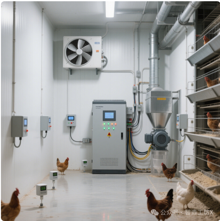
In the chicken coop, there is a PLC (master device), acting as the “manager” of the entire coop. There are also temperature sensors (slave devices), humidity sensors (slave devices), feeding motors (slave devices), ventilation fans (slave devices), and other “assistants.”
The temperature sensor stores the temperature data in its input registers. When the PLC wants to know the temperature situation, it uses function code 0x04 to issue a command to read the input registers. Once the temperature sensor receives the command, it sends its temperature data back to the PLC via the RS-485 communication line.
After receiving the temperature data, the PLC compares it with the set temperature range and finds that the temperature is a bit high. It then uses function code 0x05 to send a 1 to the coils register of the ventilation fan, instructing it to start and cool down the chicken coop. Meanwhile, the humidity sensor is also monitoring humidity in real-time, storing humidity data in its input registers. The PLC reads the humidity data in the same way, and if the humidity is too high, it uses function code 0x06 to write a new speed value to the holding register of the feeding motor, slowing down the feeding rate to prevent the chickens from being unable to eat due to high humidity and temperature.
In this case, the master-slave architecture clarifies the communication relationship between the PLC and various devices; register types ensure that different types of data are appropriately stored; function codes enable data reading and device control; and RS-485 communication ensures accurate data transmission. These core elements work together to create an intelligent and efficient automated chicken farm. Without the close cooperation of these core elements, the entire chicken farm could fall into chaos, potentially harming the chickens.
Isn’t it fascinating? These core elements are like LEGO blocks that, when assembled together, can build various automated systems, ensuring devices behave properly and the production process runs smoothly.
6
Summary and Practice: Internalizing Core Elements and Getting Hands-On
Alright, that’s it for today’s core elements! Let’s review together: the master-slave architecture is the “skeleton” of the MODBUS protocol, supporting the framework of device communication; register types are the “flesh and blood,” storing various critical data; function codes are the “nerves,” transmitting commands and information; and data transmission is the “blood vessels,” ensuring smooth data flow. These core elements are interrelated and work together to form a complete system of the MODBUS protocol. Without these core elements, the MODBUS protocol would fall apart, and devices would be unable to communicate effectively.
If you can firmly remember these core elements, you will have already established a solid footing in the world of the MODBUS protocol! However, merely remembering is not enough; you need to practice hands-on. You can look for small devices that support the MODBUS protocol around you, set up a simple communication network, and use upper computer software or programming tools to try reading device data and issuing commands based on the knowledge discussed today. Trust me, practice makes perfect; as long as you are willing to get hands-on, you will soon master the MODBUS protocol and lay a solid foundation for future industrial automation projects!
If you encounter any problems during practice or have any questions about today’s content, feel free to leave a comment, and we can brainstorm together to solve the issues! See you next time, and remember to ponder these core elements!