Source: Sensor Technology
A bus is a common communication line for transmitting information between various functional components of a computer. It consists of a bundle of wires and can be classified into data bus, address bus, and control bus based on the type of information transmitted. The data bus is used to transmit data, the address bus transmits data addresses, and the control bus carries control signals.
A bus is an internal structure that serves as a common channel for transmitting information between the CPU, memory, input, and output devices. The various components of the host are connected through the bus, and external devices connect to the bus via the corresponding interface circuits, forming the computer hardware system.
In a computer system, the common path for transmitting information between various components is called a bus. Microcomputers use a bus structure to connect various functional components.
Working Principle of the Bus
When the bus is idle (other devices are connected to the bus in a high-impedance state) and a device wants to communicate with a target device, the initiating device drives the bus and sends out the address and data. Other devices connected to the bus in a high-impedance state will receive (or can receive) the data on the bus if they detect address information that matches their own. The sending device completes the communication and releases the bus (output becomes high-impedance).
Classification of Buses
By Function and Specification
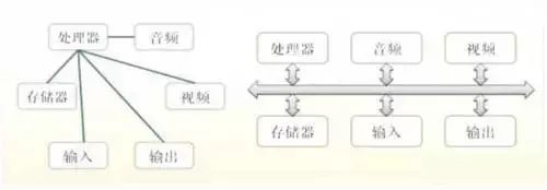
Figure 1: The Position and Relationship of Three Types of Buses in Microcomputer Systems
(1) Chip Bus (C-Bus), also known as component-level bus, is an information transmission path that connects various different chips to form a specific functional module (such as a CPU module). Its width can be 8, 16, 32, or 64 bits. Some popular internal bus technologies include I2C bus, SCI bus, etc.
(2) Internal Bus (I-Bus), also known as system bus or board-level bus, is the information transmission path between various plug-in modules in a microcomputer system. For example, the transmission path between the CPU module and memory module or I/O interface module. Common types include PC bus, AT bus (ISA bus), PCI bus, etc.
(3) External Bus (E-Bus), also known as communication bus, is the information transmission path between microcomputer systems or between microcomputer systems and other systems (instruments, meters, control devices, etc.), such as EIA RS-232C, IEEE-488, etc.
Among them, the system bus is what is commonly referred to as the bus, which generally includes three different functional buses: data bus (DB), address bus (AB), and control bus (CB).
In some systems, the data bus and address bus are multiplexed, meaning that the signals appearing on the bus at certain times represent data while at other times they represent addresses; while in other systems, they are separate. The address bus and data bus of the 51 series microcontroller are multiplexed, while the buses in a typical PC are separate.
The “Data Bus (DB)” is used to transmit data information. The data bus is a bi-directional tri-state bus, which means it can transmit data from the CPU to memory or other components such as I/O interfaces, and it can also receive data from other components back to the CPU.
The bit width of the data bus is an important indicator of the microcomputer, usually consistent with the word length of the microprocessor. For example, the Intel 8086 microprocessor has a word length of 16 bits, and its data bus width is also 16 bits.
It should be noted that the meaning of data is broad; it can be actual data, instruction codes, status information, or even control information. Therefore, in practical work, the data transmitted on the data bus is not necessarily just actual data.
The “Address Bus (AB)” is specifically used to transmit addresses. Since addresses can only be sent from the CPU to external memory or I/O ports, the address bus is always unidirectional tri-state, which is different from the data bus.
The bit width of the address bus determines the size of the memory space that the CPU can directly address. For example, an 8-bit microcomputer with a 16-bit address bus can address a maximum space of 2^16 = 64KB, while a 16-bit microcomputer has a 20-bit address bus, allowing it to address 2^20 = 1MB. Generally, if the address bus is n bits wide, the addressable space is 2^n bytes.
The “Control Bus (CB)” is used to transmit control signals and timing signals. Control signals include those sent from the microprocessor to memory and I/O interface circuits, such as read/write signals, chip select signals, interrupt response signals, etc.; there are also signals fed back to the CPU from other components.
For example, interrupt request signals, reset signals, bus request signals, device ready signals, etc. Thus, the direction of transmission on the control bus depends on the specific control signals, which are generally bi-directional. The bit width of the control bus should be determined based on the actual control needs of the system. In practice, the specifics of the control bus mainly depend on the CPU.
By Transmission Method
Can be classified into serial bus and parallel bus. In a serial bus, binary data is sent bit by bit through a single data line to the target device; parallel bus usually has more than two data lines. Common serial buses include SPI, I2C, USB, and RS232. Common parallel buses include VME bus and PCI bus. Serial buses generally transmit data faster than parallel buses, with the clock for parallel buses usually at 33MHz or 66MHz.
By Clock Signal Independence
Can be divided into synchronous bus and asynchronous bus. Synchronous buses have clock signals independent of data, while asynchronous buses extract clock signals from the data. I2C bus, SPI bus, PCI bus, and CPCI bus are synchronous serial buses, while SCI bus, IEEE 488, ANSI X3.131-1986 SCSI bus, VME bus, and RS232 use asynchronous serial buses.
Main Technical Indicators of Buses
(1) Bandwidth of the Bus (Data Transfer Rate)
The bandwidth of the bus refers to the amount of data transmitted on the bus in a unit of time, that is, the maximum steady-state data transfer rate per clock cycle.
Two closely related factors are the bit width of the bus and the operating frequency of the bus, with the relationship being:
Bus bandwidth = Bus operating frequency * Bus bit width / 8
Or
Bus bandwidth = (Bus bit width / 8) / Bus cycle
(2) Bit Width of the Bus
The bit width of the bus refers to the number of bits of binary data that can be transmitted simultaneously, or the bit width of the data bus, i.e., the concept of bus width such as 32 bits, 64 bits, etc. The wider the bus bit width, the greater the data transfer rate per second, and the wider the bus bandwidth.
(3) Operating Frequency of the Bus
The operating clock frequency of the bus is measured in MHz; the higher the operating frequency, the faster the bus operates, and the wider the bus bandwidth.
Advantages and Disadvantages of Bus Structures
Main Advantages of Using Bus Structures:
1. Simplifies hardware design. It facilitates the use of modular design methods. Microcomputer designs based on the bus only need to produce CPU plug-ins, memory plug-ins, and I/O plug-ins according to these specifications and connect them to the bus to work, without considering the detailed operations of the bus.
2. Simplifies system structure. The entire system structure is clear, with fewer connections, and the baseboard connections can be printed.
3. Good system scalability. For scale expansion, it only requires adding more same-type plug-ins. For functional expansion, it only needs to design new plug-ins according to bus standards, with no strict limitations on where to insert the plug-ins in the machine.
4. Good system update performance. Since the CPU, memory, I/O interfaces, etc., are all connected to the bus according to bus specifications, as long as the bus is properly designed, new plug-ins can be designed at any time along with the progress of processor chips and other related chips, and new plug-ins can be inserted into the baseboard for system updates, generally without needing to change other plug-ins and baseboard connections.
5. Facilitates fault diagnosis and maintenance. Using a motherboard test card, it is easy to locate the faulty part and identify the type of bus.
Disadvantages of Using Bus Structures:
1. The use of the bus for transmission is time-sharing. When multiple master devices request the use of the bus simultaneously, bus arbitration must occur.
2. The bandwidth of the bus is limited, and if the hardware devices connected to the bus do not have a resource control mechanism, it can easily cause information delays (which can be critical in certain time-sensitive applications).
3. Devices connected to the bus must have an information filtering mechanism to determine whether the information is intended for them.
Classification of Embedded Bus Technology
Internal Bus, System Bus, and External Bus
Internal Bus
Internal Bus: Connects all structural units inside the processor. Its width can be 8, 16, 32, or 64 bits. Some popular internal bus technologies include:
I2C Bus
The I2C (Inter-IC) bus was introduced over a decade ago by Philips and has become a widely adopted new bus standard in the field of microelectronic communication control in recent years.
It is a special form of synchronous communication that has advantages such as fewer interface lines, simplified control methods, small device packaging, and relatively high communication rates. In master-slave communication, multiple I2C bus devices can connect to the I2C bus simultaneously, identified by their addresses.
SPI Bus
The Serial Peripheral Interface (SPI) bus technology was introduced by Motorola as a synchronous serial interface. Most MCUs produced by Motorola are equipped with SPI hardware interfaces, such as the 68 series MCUs.
The SPI bus is a three-wire synchronous bus, and because of its strong hardware functionality, the software related to SPI is relatively simple, allowing the CPU more time to handle other tasks.
SCI Bus
The Serial Communication Interface (SCI) is also introduced by Motorola. It is a general asynchronous communication interface (UART), similar to the asynchronous communication function of the MCS-51.
System Bus
The system bus, also known as internal bus or board-level bus, is used to connect various functional components of a microcomputer to form a complete microcomputer system. Common types include PC bus, AT bus (ISA bus), PCI bus, etc.
The information transmitted on the system bus includes data information, address information, and control information. Therefore, the system bus includes three different functional buses: data bus (DB), address bus (AB), and control bus (CB).
Currently, the ISA bus (Industrial Standard Architecture) is a popular system bus technology. The ISA bus standard was established by IBM in 1984 to launch the PC/AT machine, hence it is also called the AT bus. It is an extension of the XT bus to meet the requirements of 8/16-bit data buses.
It was widely used during the 80286 to 80486 era, to the extent that ISA bus slots are still retained in current Pentium machines. The ISA bus has 98 pins.
For more content, please visit
Guangdong Optoelectronic Network www.gdoet.org