The following outlines the goals, main challenges, solutions of AUTOSAR, and the benefits brought by these solutions.
-
Handling the rapidly increasing electrical/electronic complexity related to systems;
-
Flexibility in implementing product modifications, upgrades, and updates;
-
Improving the scalability and cross-compatibility of software solutions;
-
Enhancing the software quality and reliability of systems;
-
Enabling error detection in the early stages of development.
AUTOSAR Architecture
Significance of the AUTOSAR Architecture
The number of electronic/electrical systems in modern vehicles and the complexity of these systems are increasing. The growing complexity of vehicle networks is the driving force behind the development of AUTOSAR.
Modern vehicles each have over one hundred ECUs, each with a wide range of functions. Without following standards, when the ECU hardware design changes, software development is likely to require rewriting.

AUTOSAR is specifically designed for automotive ECUs and has the following characteristics:
-
Strong interaction with hardware (sensors and actuators),
-
Connection to vehicle networks such as CAN, LIN, FlexRay, or Ethernet,
-
Microcontrollers with limited computing power and memory resources.
-
Time-critical systems and real-time programs executed from internal memory.
Overview of the Layered AUTOSAR Architecture
The AUTOSAR architecture distinguishes between three software layers at the highest level of abstraction: application layer, runtime environment, and basic software.

Application Layer
The application layer is the top layer of the AUTOSAR software architecture, supporting the implementation of custom functionalities. This layer consists of specific software components and numerous applications, which are a set of interconnected AUTOSAR software components executing specific tasks according to instructions.
Each AUTOSAR software component encapsulates part of the functionality of the complete application software. AUTOSAR does not specify how large an AUTOSAR software component should be. Depending on the application requirements, an AUTOSAR software component may be a small, reusable function, such as lane-keeping assistance, wiper control, automatic door unlocking, etc.
Communication between software components is achieved using specific ports via the Virtual Function Bus. These ports can also facilitate communication between software components and AUTOSAR Basic Software (BSW).
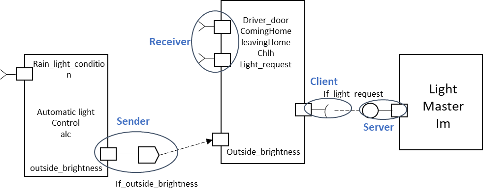
-
Client-Server Communication: The client can initiate the execution of operations through the server that supports the operation, and the server executes the operation and immediately provides the results to the client (synchronous operation call).
-
Sender-Receiver Communication: This is an asynchronous communication mode where the sender provides data required by one or more receivers.
The RTE layer provides an ECU-independent interface for application software components, providing communication services for application software components (SWC).
-
Client/Server ports, where the server is the provider of the service, and the client is the user of the service. -
Sender/Receiver ports, where the sender sends information to one or more receivers.
AUTOSAR Basic Software (BSW) is further divided into three layers:
-
Service Layer,
-
ECU Abstraction Layer,
-
Microcontroller Abstraction and Complex Device Drivers (CDD).
Each layer has different functional modules, and the interaction between modules in different layers is specified.

The Microcontroller Abstraction Layer is the lowest layer of the basic software, meaning that MCAL modules can directly access hardware resources. MCAL includes internal drivers that are software modules for directly accessing the µC and internal peripherals.
As the name suggests, the MCAL layer makes the upper layers independent of HW (MCU).
-
Operating system functions -
Vehicle networking communication and management services -
Memory services (NVRAM management) -
Diagnostic services (UDS, error handling, memory) -
ECU state management, mode management -
Monitoring of logical and time program flows (WdgM)
Detailed Description of the AUTOSAR COM Module
This section lists all functional modules of the AUTOSAR COM module. For the placement of the AUTOSAR COM module in the communication stack, please refer to the figure below.
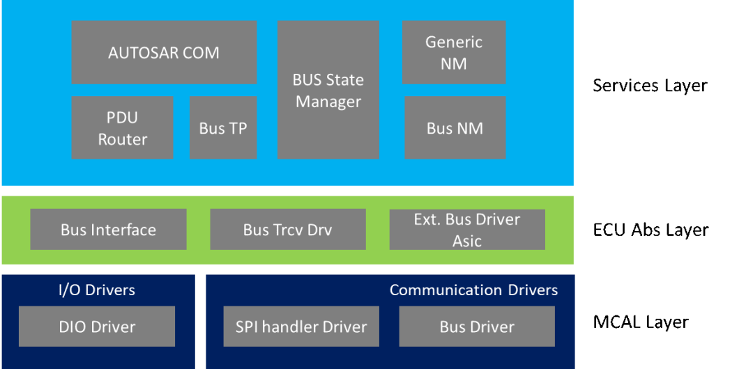
This module is part of the AUTOSAR MCAL layer (e.g., CanDrv, LinDrv, FrDrv), which interacts directly with the underlying hardware of the ECU and provides an interface independent of hardware for its upper layers. This module depends on the hardware, and the driver code may vary based on the underlying hardware. BusIf is the only module that can access this bus driver.
Layered Software Architecture of Multi-core Microcontrollers
As the demand for computing resources in the automotive field increases, OEMs and Tier 1 suppliers are gradually introducing the use of multi-core ECUs in their electronic architectures. Moreover, these multi-core ECUs provide a foundation for the introduction of new functionalities, such as the implementation of functional safety requirements.
AUTOSAR version 4.0 introduced support for multi-core embedded RTOS. New concepts such as multi-core startup/shutdown and inter-core communication (IOC) were introduced in the AUTOSAR 4.0 specification to extend the single-core operating system specifications.
The improved AUTOSAR architecture is shown below:

Functional Safety
The safety of the system depends on the expected operation of specific functionalities. The functional safety standard ISO26262 originates from IEC-61508, guiding us to adopt an automotive-specific risk-based approach to developing electrical and electronic (E/E) systems. The goal of functional safety is to execute the expected operations correctly; otherwise, the system will fail and transition to a predictable safe state. Software is one of the parameters that affect system-level complexity. New technologies and concepts in software development can be used to minimize complexity, thus contributing to functional safety. AUTOSAR R4.0 considers functional safety aspects that are important for modern automotive software development.
There are many development methods under AUTOSAR to detect and report functional errors at each stage of software development. Even though functional safety applies and is followed at every stage of product development until it involves the user.
The following is a typical list of interference sources that lead to errors detected by E2E protection:
SW-related sources:
S1. Most errors in the generated RTE,
S2. Errors in the COM with partial generation and partial manual coding
S3. Network stack errors
S4. Errors in generated IOC or OS
Hardware-related resources:
H1. Hardware network failures
H2. Electromagnetic interference in the network
H3. Microcontroller failures during context switching or communication between cores
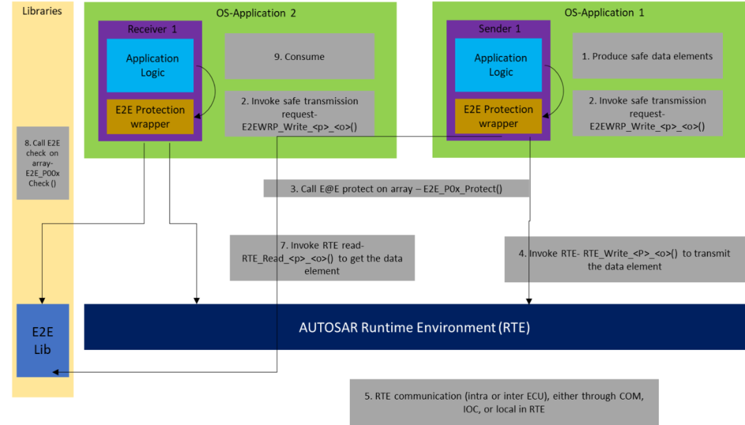
An example of a practical method adopted when developing SWC interfaces is to provide end-to-end protection for data integrity.
For each RTE Write or Read function that transmits safety-related data (such as Rte_Write_
_
-
The encapsulation function calls the AUTOSAR E2E library.
-
The encapsulation function is part of the software component and is preferably generated.
-
The encapsulation function has the same signature as the corresponding RTE function, except that E2EPW_ replaces Rte_.
-
The E2EPW_ function is called by the application logic of the SW-C, and the encapsulation function performs protection/checks and internally calls the RTE function.
-
For inter-ECU communication, the data elements sent through E2E protection are byte arrays. The byte arrays are copied to the COM I-PDU without any changes.
ECU Design and Configuration Methods
AUTOSAR provides a generic technical approach for system development steps. The diagram shows an overview of the design steps for building an ECU using AUTOSAR technology. This means that these steps must be performed for each ECU in the system.
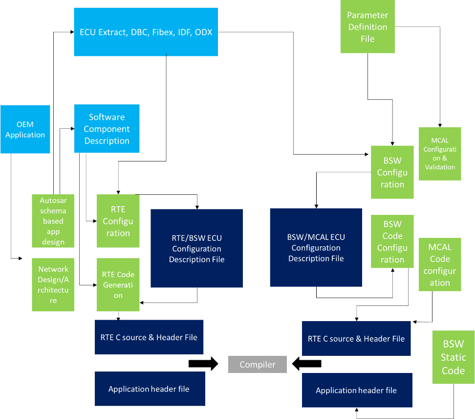
It is important to note that AUTOSAR does not specify the exact order of executing development activities. AUTOSAR does not describe processes or commercial models, nor does it define “roles” and “responsibilities.”
The following diagram is an example of a workflow that is generally followed. The diagram separately describes the development processes of BSW and application software.


The main activities at this stage are to extract ECU-specific information from the system configuration description, configure the ECU, and generate executable ECU software. The following sections will describe these activities in more detail.
Extracting ECU-specific Information
The AUTOSAR ECU Configuration Extractor tool (e.g., System Desk, Da-Vinci) extracts information from the system configuration description required for the specific ECU. This is a one-to-one copy of all elements of the system configuration description mapped to this specific ECU. The output is an ECU extract of the system configuration. Network database (e.g., CAN.dbc) files are the input for generating ECU extracts (.arxml).
Configuring (BSW) ECU
ECU configuration mainly deals with the configuration of the RTE and basic software modules. This configuration is based on the parameters available in the ECU extract of the system configuration. The available SWC implementations and the set of BSW module descriptions. BSW also includes supplier-specific ECU configurations. This is necessary because the output ECU configuration description has a flexible structure, and a fixed number of configuration parameters is not defined during ECU extraction.
During BSW configuration, communication modules, MCAL, operating systems, or AUTOSAR services must be defined.
Software Component Implementation
The initial work for SWC begins with providing the necessary parts of the software component description [SWCTempl]. That is, the internal behavior description of the component as part of the software component-related template. The internal behavior describes scheduling-related aspects of the component, i.e., runnable entities and their responding events. Moreover, the behavior specifies how the component (or more accurately which runnable component) responds to received data elements and events. However, it does not describe the detailed functional behavior of the component.
Copyright Notice: Compiled from foreign materials
Finally, the editor has also compiled a wave of AUTOSAR materials, as shown in the figure below.Simply share this document to your circle of friends to gather 20 likes, and send it to the editor in the background to get the download link.


Functional Safety – Safety Analysis
Detailed Explanation of SPI, UART, I2C Buses
Understanding ASPICE
Detailed Explanation of Automotive Bootloader Design
Research on the Safety of Tesla Autopilot System | Download dbc
Detailed Explanation of Functional Safety Concept Stage
Detailed Revelation of Volkswagen ID.4’s High Voltage System
Tesla Model 3’s BMS System