1. Introduction to Cortex-M0 Processor Core Exception Interrupts
The Cortex-M0 core is equipped with an exception response system that supports numerous system exceptions and external interrupts. Among them, numbers 1-15 correspond to system exceptions, while numbers greater than or equal to 16 are all external interrupts. The smaller the numerical value of the priority, the higher the priority. Except for a few exceptions with fixed priorities, the priorities of other exceptions are programmable.
Since chip design can modify the hardware description source code of the core, the number of supported interrupt sources is often less than 240 after the chip is made, and the number of priority bits is ultimately determined by the chip manufacturer.
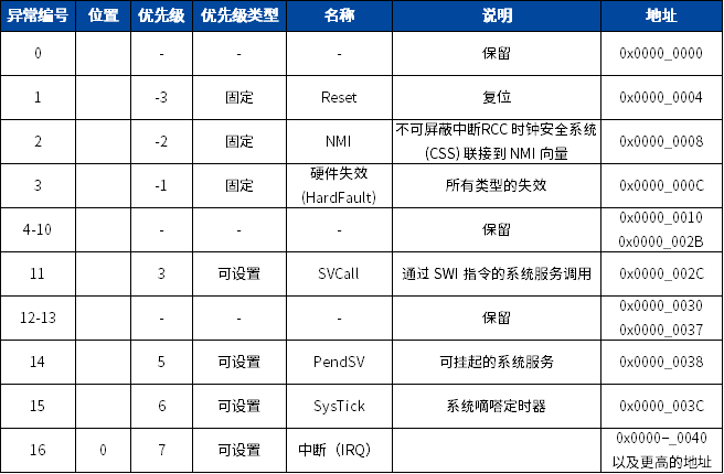
Type numbers 1-15 correspond to system exceptions, which are described in Chapter 12
Reset is triggered during power on/off, when NRST is pulled low, during watchdog reset, or soft reset. When a reset occurs, the processor stops all operations and treats the reset as a special form of exception, entering the corresponding interrupt function. When the reset is removed, it restarts execution from the address provided by the reset entry in the vector table, and the chip begins execution anew.
NMI Non-Maskable Interrupt (NMI) can be generated by peripherals or triggered by software. This is the highest priority exception interrupt except for reset, NMI is always enabled, and its priority is fixed at -2. The clock security mechanism of CSS will enter this interrupt when it determines a clock failure. NMI cannot: 1. be masked; its execution cannot be interrupted by any other exception; 2. be preempted by any exception other than reset.
HardFault HardFault is an exception that occurs due to an error during normal operation or during exception handling. The priority of HardFault is fixed at -1, indicating that its priority is higher than any configurable exception.
SVCall Supervisor Call (SVC) exception is an exception triggered by the SVC instruction. In an OS environment, applications can use the SVC instruction to access OS kernel functions and device drivers.
PendSV PendSV is an interrupt-driven system-level service request. In an OS environment, when no other exception is valid, PendSV is used for task switching.
SysTick SysTick is an exception generated when the system timer reaches zero; software can also generate a SysTick exception. In an OS environment, the processor can use this exception as a system tick.
Interrupt (IRQ) Interrupt (or IRQ) is an exception issued by peripherals or generated by software requests. In the system, peripherals use interrupts to communicate with the processor, and in the interrupt function, flags can be queried and cleared.
2. HardFault Exception
HardFault (hardware error, also translated as hard error) occurs due to errors in programs written on the MCU, and hardware error handling is almost the highest priority, with a priority of -1, only reset and non-maskable interrupts (NMI) can preempt it. When it occurs, it indicates that there is a problem with the processor, and urgent repair measures need to be taken.
There are many possible causes for HardFault errors, and how to quickly locate the problematic code that caused HardFault in cases of large code volumes becomes a critical issue.
This article will take the MM32F0130 series MCU as an example, using the Keil-MDK development environment to summarize the debugging and locating methods for HardFault. It can also serve as a reference for other Cortex-M0 (M3, M4) core processors and other development environments.
2.1 Possible Causes
The “ARM Cortex-M0 Authority Guide” mentions the following main points that can cause HardFault in the Cortex M0 core:
-
Illegal memory access
-
Unaligned data access
-
Bus return error
-
Stack corruption during exception handling
-
Program crashes in certain C functions
-
Accidentally attempting to switch to ARM state
-
Executing system service call instructions (SVC) at the wrong priority
From a software perspective, possible causes of HardFault include:
-
Array out of bounds
-
Dangling pointers
-
Uninitialized hardware being operated on, or lack of interrupt service functions, etc.
-
Task stack overflow
-
Incorrect interrupt service function settings
-
Clock exceptions
Note: Only reset and NMI can preempt the fixed-priority HardFault handler. HardFault can preempt any exceptions other than reset, NMI, or other hard faults.
2.2 Possible Exceptions
If a bus error occurs while executing the NMI or HardFault handler, or when returning from an exception using MSP and popping PSR, the processor enters a locked state. When the processor is in a locked state, it does not execute any instructions. The processor remains in a locked state until one of the following occurs:
-
A reset occurs
-
The debugger terminates the locked state, resulting in a simulation abort
-
An NMI occurs, and the current lock is in the HardFault handler
Note: If the locked state occurs in the NMI handler, subsequent NMIs cannot release the processor from the locked state.
In the application, when the processor is in a locked state, it will continuously execute in the void HardFault_Handler(void) function.
void HardFault_Handler(void)
{  /* Go to infinite loop when Hard Fault exception occurs */
  while (1)
  {
  }
}
Below is an example of an out-of-bounds array code running on the MM32F0130, detailing the locating steps:
void StackTest(void)
{    int data[3],i;
    for(i=0; i<10000; i++)
    {
    data[i]=1;
    }
}
3. Methods and Steps to Find HardFault
In actual environments, due to testing high-voltage products often being unable to connect to a debugger, code is needed to locate the target statement address and save it through certain means:
In MM32F0130, you need to modify the startup file startup_mm32f013x.s first:
HardFault_Handler\
            PROC
            IMPORT  hard_fault_handler_c; function declaration
            MOVS r0, #4                   ; determine whether to use MSP or PSP
            MOV r1, LR
            TST r0, r1
            BEQ stacking_used_MSP        ; if using MSP
            MRS R0, PSP              ; otherwise, use PSP, assign PSP address to R0
            B get_LR_and_branch          ; jump to HardFault interrupt program
            stacking_used_MSP
            MRS R0, MSP                   ; assign MSP address to R0
            get_LR_and_branch
            MOV R1, LR

            BL hard_fault_handler_c
            ENDP
This code will determine whether the current stack is using MSP or PSP, and then pass the stack parameters to the hard_fault_handler_c function, which is defined as follows:
void hard_fault_handler_c(unsigned int * hardfault_args, unsigned lr_value)
{ unsigned int stacked_r0; // stacked r0
unsigned int stacked_r1; // stacked r1
unsigned int stacked_r2; // stacked r2
unsigned int stacked_r3; // stacked r3
unsigned int stacked_r12; // stacked r12
unsigned int stacked_lr; // stacked lr
unsigned int stacked_pc; // stacked pc
unsigned int stacked_psr; // stacked psr
stacked_r0 = ((unsigned int) hardfault_args[0]);
stacked_r1 = ((unsigned int) hardfault_args[1]);
stacked_r2 = ((unsigned int) hardfault_args[2]);
stacked_r3 = ((unsigned int) hardfault_args[3]);
stacked_r12 = ((unsigned int)hardfault_args[4]);
stacked_lr = ((unsigned int) hardfault_args[5]);
stacked_pc = ((unsigned int) hardfault_args[6]);
stacked_psr = ((unsigned int) hardfault_args[7]);
while(1)
{
printf("[Hard fault handler]\r\n");
printf("R0 = %x\r\n", stacked_r0);
printf("R1 = %x\r\n", stacked_r1);
printf("R2 = %x\r\n", stacked_r2);
printf("R3 = %x\r\n", stacked_r3);
printf("R12 = %x\r\n", stacked_r12);
printf("Stacked LR = %x\r\n", stacked_lr);
printf("Stacked PC = %x\r\n", stacked_pc);
printf("Stacked PSR = %x\r\n", stacked_psr);
printf("SCB_SHCSR=%x\r\n",SCB->SHCSR);
printf("Current LR = %x\r\n", lr_value);
}
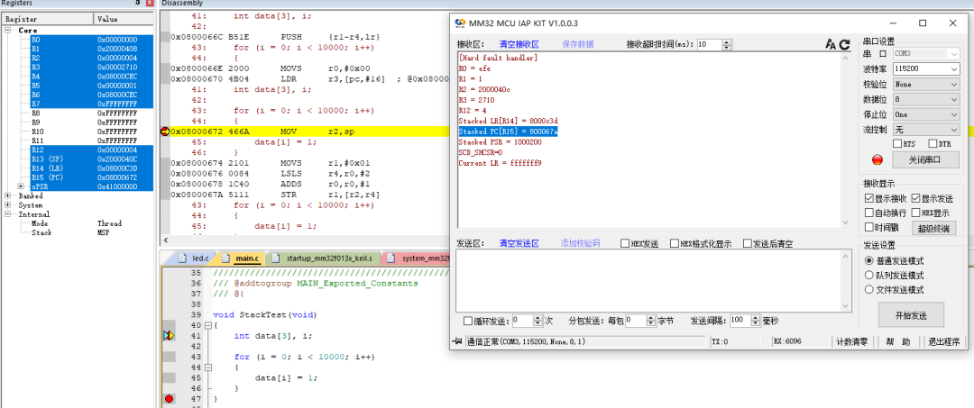
}When the processor enters HardFault, it will print R0~R3, R12, LR, PC information via the serial port, allowing for issue code investigation based on the register information.
When the processor handles exceptions, unless the exception is a terminal chained exception or a late exception, the processor pushes all information onto the current stack (stacking). The structure of 8 data words is called a stack frame, and the stack is aligned to double-word addresses.
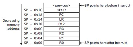
After stacking, the stack pointer immediately points to the lowest address unit of the stack frame. The stack contains the return address, which is the address of the next instruction in the aborted program. This value is returned to PC during the exception return, allowing the aborted program to resume execution.
As shown in the figure, connecting the simulator to view the assembly address can help identify the program issue. Based on the PC pointer address, the problematic function can be found in the generated .map file of the program.
4. Recommendations for Handling
Based on the above locating methods, it is possible to determine what kind of situation caused the exception. During programming, it is necessary to avoid the aforementioned exceptional situations. However, in complex and harsh environments, HardFault interrupts may be triggered with low probability. Reset or jump instructions can be added in functions, and the specific implementation methods should be evaluated based on the application and usage environment.
Author|Miss Lingdong
Source|Jishu Community
Copyright belongs to the original author, please contact for deletion if there is infringement
END


关于安芯教育


安芯教育是聚焦AIoT(人工智能+物联网)的创新教育平台,提供从中小学到高等院校的贯通式AIoT教育解决方案。
安芯教育依托Arm技术,开发了ASC(Arm智能互联)课程及人才培养体系。已广泛应用于高等院校产学研合作及中小学STEM教育,致力于为学校和企业培养适应时代需求的智能互联领域人才。