Name: Voltage Meter Design Using TLC5510 and LCD1602 Verilog Code for Quartus on Daxi Watermelon Development Board
Software: Quartus
Language: Verilog
Code Function:
Voltage meter based on TLC5510 and LCD1602 display
1. Design driver code for AD chip TLC5510
2. Convert analog signals to digital signals (AD values) using TLC5510
3. Convert digital signals (AD values) to voltage values based on reference voltage
4. Display AD values and voltage values using LCD1602
5. Connect the external TLC5510 chip module to the development board’s IO pins for physical verification
This code has been verified on the Daxi Watermelon development board, as shown below. Other development boards can modify the pin assignment accordingly: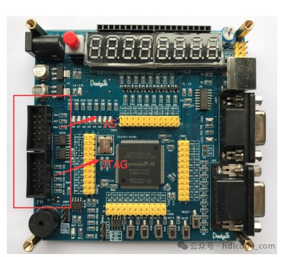
1. TLC5510
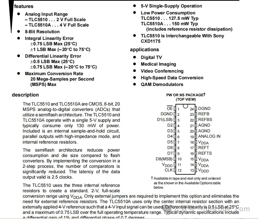
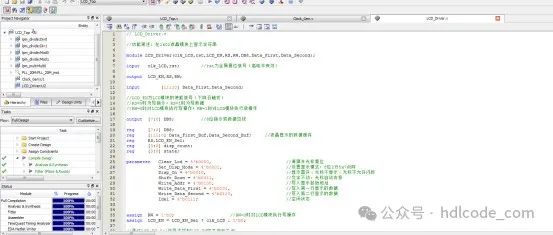
2. Project Files
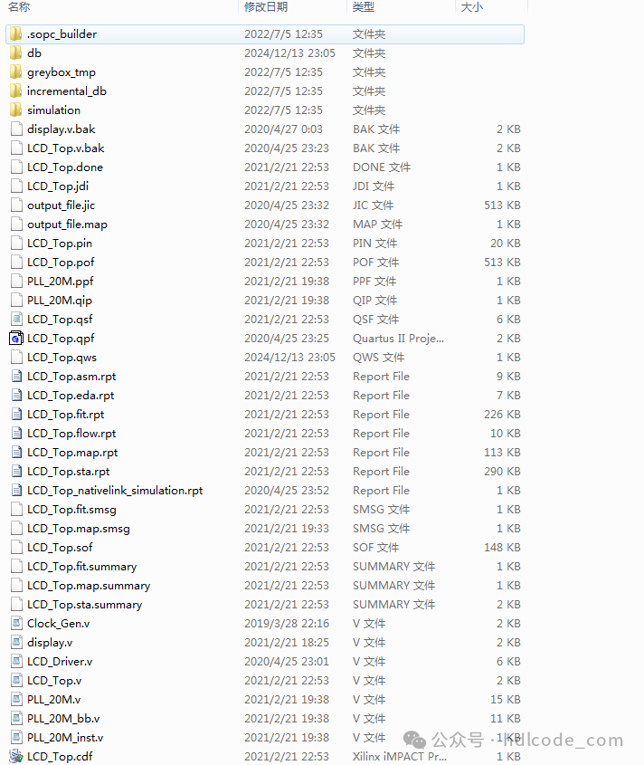
3. Program Files
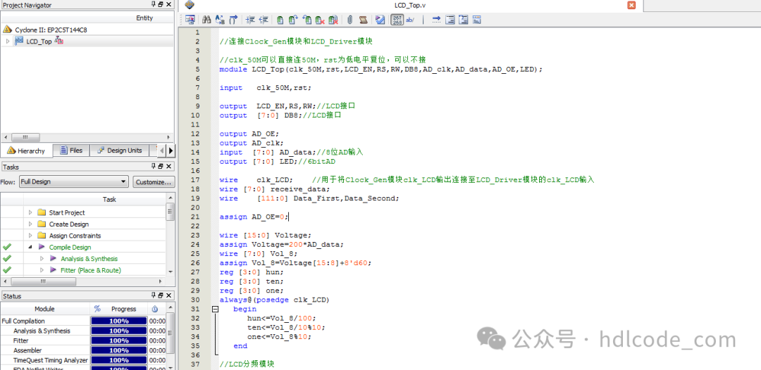
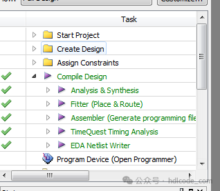
4. Program Compilation
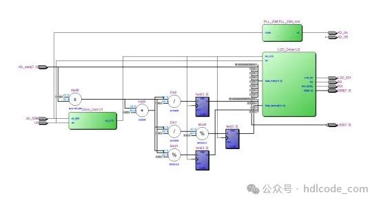
5. RTL Diagram
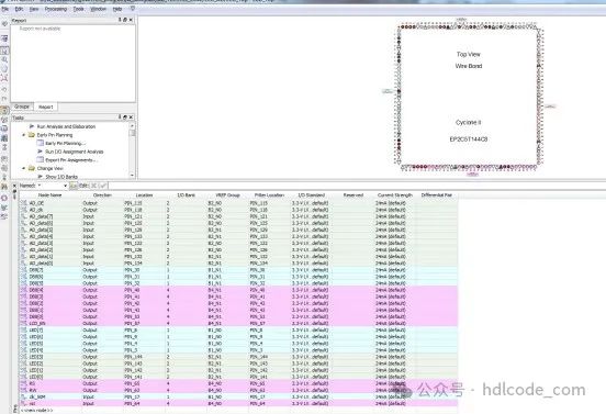
6. Pin Assignment
Partial code display:
/**************** Generate 500Hz clock signal for LCD_Driver module **************/
module Clock_Gen(clk_50M,rst,clk_LCD);
input   clk_50M,rst;                // rst is the global reset signal (active high)
output  clk_LCD;
wire    clk_counter;
reg     [11:0]  cnt;                  // Count and divide the clock
wire    clk_equ;
reg     [9:0] count;
reg     clk_BUF;
parameter       counter = 48;     // How much to divide
/********************************************************************************
** Module Name: Frequency Divider
** Function Description: Achieve frequency division function through counter.
********************************************************************************/

always@(posedge clk_50M)
begin
if(!rst)                            // Active low reset
cnt <= 12'd0;
else if(clk_equ)
cnt <= 12'd0;
else
    cnt <= cnt + 1'b1;
end
assign clk_equ = (cnt == counter);
assign clk_counter = clk_equ;

always @(posedge clk_counter or negedge rst)
begin                                   // Generate 500Hz clock using counter
    if(!rst)
        begin
        clk_BUF <= 1'b0;
        count <= 10'b0;
        end
