“工控有得聊”是机械工业出版社“机工工控”“机工通信”品牌旗下专业资讯和服务平台,致力于帮助读者在电气、通信、自动化领域里,紧跟前沿资讯,掌握核心技术,快速提升专业素养。点击蓝色微信名可快速关注我们。In today’s rapidly evolving technological landscape, embedded systems play an increasingly important role in our lives. From smartphones to automotive electronics and IoT devices, embedded technology is ubiquitous, driving the progress of modern society. With the rise of open-source hardware and software, RISC-V, as an emerging open-source instruction set architecture (ISA), has garnered widespread attention and rapid adoption in the industry due to its flexibility and scalability.
The HPM6750 microcontroller is a high-performance microcontroller suitable for various applications in industrial, automotive, and communication fields. When developing across platforms, developers need to pay attention to key aspects such as hardware compatibility, software toolchain selection, and development environment configuration.
This article comprehensively demonstrates the development process using the HPM6750 microcontroller through a practical GPIO output application example. Whether you are a developer exploring the RISC-V ecosystem for the first time or a seasoned engineer seeking high-performance, open-source solutions, this article will pave a clear and efficient development path for you!

Overview of GPIO Output Application Example for HPM6750
This example is implemented on the Wildfire HPM6750IVM (BTB interface) development board, using the Wildfire fireDAP downloader (high-speed version) as the emulator, along with a JTAG-UART adapter board connecting the emulator to the development board; additionally, three Type-C data cables are used for connecting the fireDAP downloader, the development board’s USB-OTG interface, and the power interface PWR of the development board to the computer’s USB interface. The buttons KEY1, KEY2, and KEY3 are connected to the HPM6750’s WBUTN (with wake-up function), PZ09, and PZ11 GPIO pins, respectively, which have internal pull-up resistors. The LED indicators LED4, LED5, and LED6 are connected to the HPM6750’s PB29, PB30, and PB31 GPIO pins, respectively.
After powering on the program or pressing the RES reset button on the development board, the LED4, LED5, and LED6 indicators will flash at the same frequency for a few seconds, after which the three indicators will remain lit. When the KEY1, KEY2, and KEY3 buttons are pressed, the LED4, LED5, and LED6 indicators will toggle, meaning the indicator will turn off when the button is pressed and turn on again when the button is pressed a second time.
The system architecture of HPM6750EVK is shown in Figure 1.
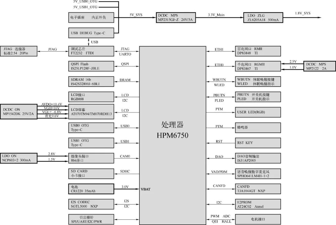
Figure 1 HPM6750EVK System Architecture
The GPIO output application example for HPM6750 aims to demonstrate how to control LED lights and respond to button input interrupts using the GPIO interface on the HPM6750 platform. Through this design, one can gain a deeper understanding of GPIO configuration, interrupt management, and basic input/output control on the HPM6750 platform.
1. Design Objectives
Control of LED lights: Achieve control over LED lights through GPIO output functionality, including turning them on and off.
Response to button input: Implement response to button operations through GPIO input and interrupt functionality, changing the state of the corresponding LED lights when button operations are detected.
2. Design Implementation
(1) Hardware Configuration
GPIO Configuration: Use the GPIO0 controller of HPM6750 to configure GPIO pins for 3 LED lights and 3 buttons. The LED lights are connected to GPIOB pins 29, 30, and 31, while the buttons are connected to GPIOZ pins 3, 9, and 11.
Interrupt Configuration: Configure falling edge-triggered interrupts for GPIOZ pins 3, 9, and 11 to detect button press actions.
(2) Software Design
LED Blinking Test: The test_gpio_toggle_output function toggles the state of the LED lights in a loop to achieve a blinking effect, verifying the GPIO output functionality.
Button Interrupt Response: The test_gpio_input_interrupt function configures the button GPIO pins as input mode and sets the interrupt trigger conditions. The isr_gpio interrupt service routine responds to button interrupts by toggling the state of the corresponding LED lights.
Debounce Handling: The isr_gpio interrupt service routine does not implement debounce logic directly. In practical applications, software delays or other debounce techniques can be used to improve the stability of button responses.
3. Main Functions
(1) board_init: Performs board-level initialization, such as clock configuration and interrupt system initialization.
(2) test_gpio_toggle_output: Tests GPIO output functionality to achieve LED blinking.
(3) test_gpio_input_interrupt: Configures GPIO input and interrupts to prepare for button operations.
(4) isr_gpio: Interrupt service routine for handling button-triggered interrupts and toggling LED states.
(5) main: The main function responsible for initialization and calling test functions.
This design example demonstrates the basic application of the GPIO interface by implementing LED control and button response functionality on the HPM6750 platform. By blinking the LED lights and responding to button interrupts, it verifies the input/output control and interrupt handling capabilities of GPIO. Furthermore, this design emphasizes the importance of hardware configuration and software logic design in embedded system development. In further research, more advanced features of the HPM6750 platform, such as PWM control and ADC reading, can be explored to achieve more complex embedded system applications.
HPM6750 GPIO Output Application Hardware Design
The hardware circuit of HPM6750 with buttons is shown in Figure 2. The buttons KEY1, KEY2, and KEY3 are elastic mechanical switches, and PESD3V3L1BA is a 3.3V Transient Voltage Suppressor (TVS) diode. Transient Voltage Suppressor (TVS) diodes are semiconductor devices specifically designed to protect electronic equipment from damage caused by transient voltages and voltage spikes. They can respond quickly and suppress instantaneous overvoltages that exceed normal operating voltages, thereby protecting sensitive electronic components.
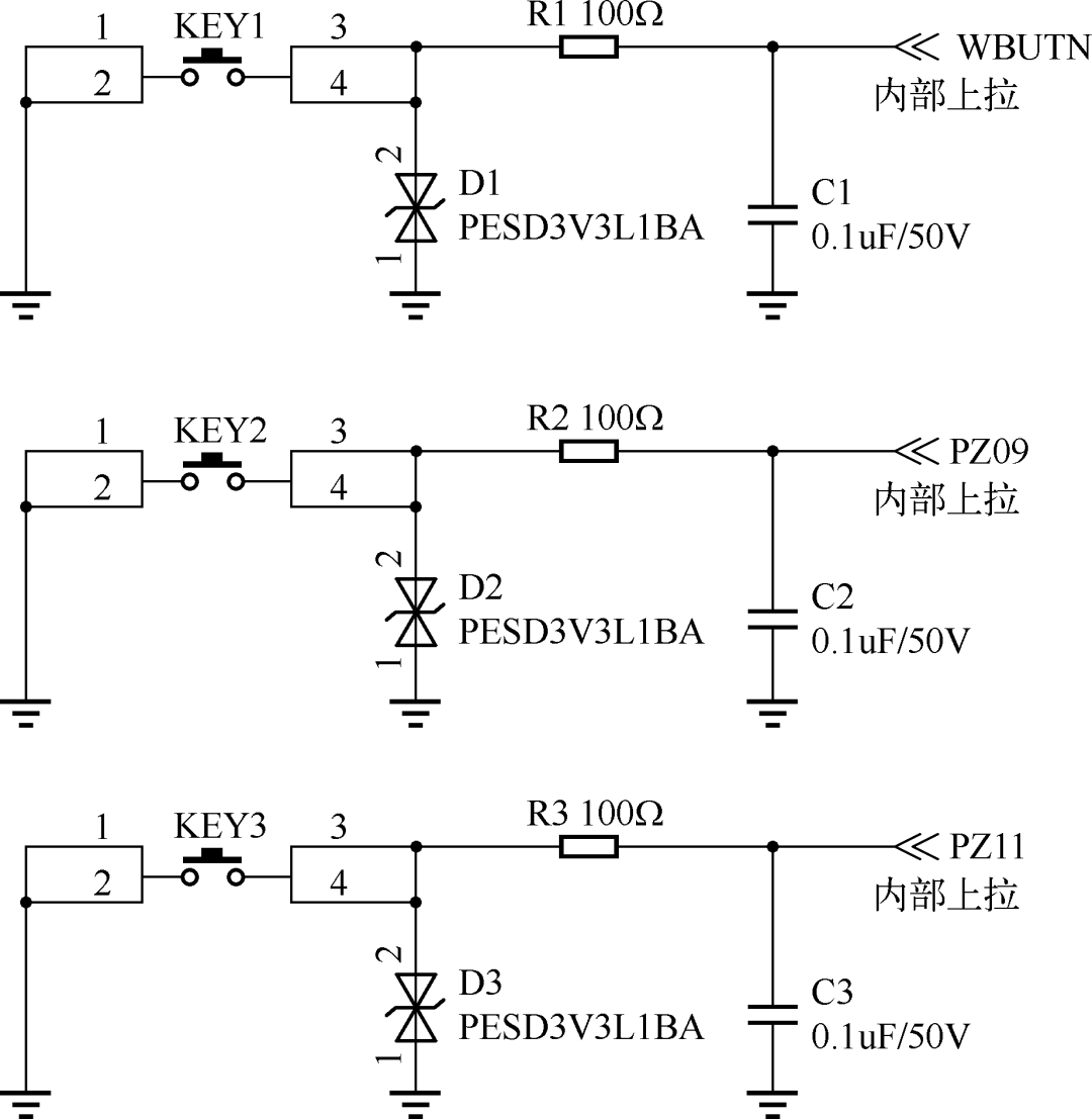
Figure 2 HPM6750 Hardware Circuit with Buttons
The hardware circuit of HPM6750 with LED lights is shown in Figure 3. The three LED indicators consist of green LED lights.
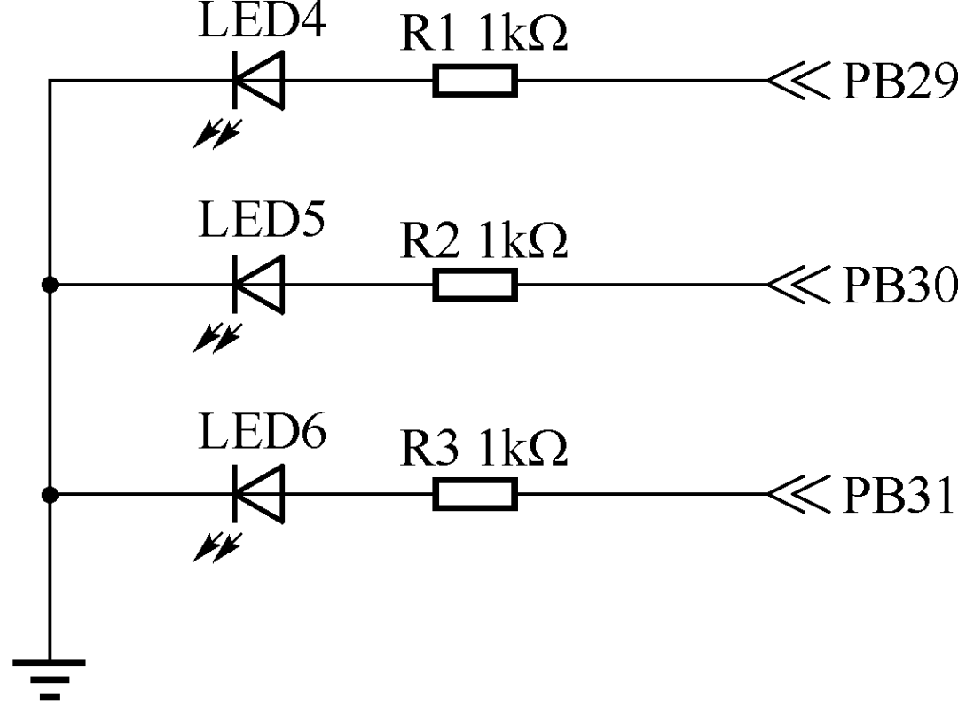
Figure 3 HPM6750 Hardware Circuit with LED Indicators
The anodes of these LEDs are connected to the GPIO pins of HPM6750. By controlling the output state of the GPIO pins, the LEDs can be turned on or off. If the connection method or pins of the LEDs in the development board used are different, only the relevant pins in the program need to be modified, while the control principle of the program remains the same.
The LED circuit is powered by a +3.3V supply. When the GPIO pin outputs 0, the LED is off; when it outputs 1, the LED is on.
HPM6750 GPIO Application Software Design
The overview of HPM6750 software design mainly revolves around two functional modules: the use of GPIO (General Purpose Input/Output) and interrupt handling. This example program demonstrates how to configure GPIO on the HPM6750 platform to control the on/off state of LED lights and how to set up and handle GPIO interrupts to respond to external button events. The detailed design steps of the software are as follows:
1. GPIO Configuration and LED Control
(1) GPIO Configuration
Header File: The program includes the gpio.h header file, which defines the GPIO controllers, indices, and pin numbers related to the LED and buttons, as well as the level state when the LED is off.
Initialization: In the test_gpio_toggle_output function, the GPIO pins corresponding to the LED are configured as output mode through the PAD register of the HPM_IOC controller, and the initial state (off) is set.
(2) LED Control
Toggling LED State: The program toggles the level state on the specified GPIO pins using the gpio_toggle_pin function to switch the LED on and off. This is implemented in the test_gpio_toggle_output function through a loop to demonstrate the blinking effect of the LED.
Delay: A delay of 500 milliseconds is implemented between LED state toggles using the board_delay_ms function to observe the blinking effect of the LED.
2. GPIO Interrupt Handling
(1) Interrupt Configuration
Input Mode: In the test_gpio_input_interrupt function, the GPIO pins related to the buttons are first configured as input mode.
Interrupt Trigger Method: The program sets the trigger method for GPIO interrupts to falling edge-triggered, meaning that when a button is pressed (the level changes from high to low), an interrupt will be triggered.
Interrupt Enable: The interrupt functionality for the GPIO pins related to the buttons is enabled by calling the gpio_enable_pin_interrupt function.
(2) Interrupt Service Routine (ISR)
Checking Interrupt Flags: In the isr_gpio function, the gpio_check_pin_interrupt_flag function is called to check if any GPIO pins related to the buttons have generated an interrupt.
Handling Interrupts: When an interrupt from a button is detected, the program toggles the state of the corresponding LED by calling the gpio_toggle_pin function and clears the interrupt flag using the gpio_clear_pin_interrupt_flag function to continue receiving subsequent interrupts.
3. Main Function
(1) Initialization: The main function first calls board_init for board-level initialization.
(2) Function Testing: It then calls the test_gpio_toggle_output and test_gpio_input_interrupt functions to test the LED blinking and button interrupt response functionalities, respectively.
(3) Infinite Loop: Finally, the main function enters an infinite loop, waiting for interrupt events to occur.
This program demonstrates how to use GPIO for basic input/output control and interrupt handling on the HPM6750 platform. By controlling the LED’s on/off state, it showcases the GPIO output functionality, while responding to button interrupts illustrates the GPIO input and interrupt handling capabilities. This provides a foundation for developing more complex embedded system applications.

Recommended Reading
 In-Depth Analysis of RISC-V Technology EcosystemComprehensive Interpretation of Theoretical Concepts + Technical Ecosystem + Development Examples!
 <Click on the book cover to purchase>
▊ “Embedded System Development Based on RISC-V Architecture”
Authors: Li Zhengjun, Li Xiaoran
This book comprehensively introduces the RISC-V architecture and its applications in embedded system development. The book is divided into 13 chapters, covering topics such as: Introduction, RISC-V Technology Ecosystem and Practice, Interrupts and Exceptions in RISC-V Architecture, RISC-V Assembly Language Programming, CH32 Embedded Microcontroller and Minimal System Design, MRS Integrated Development Environment, CH32 General Purpose Input/Output Interface, CH32 External Interrupts, CH32 Timer System, CH32 General Synchronous and Asynchronous Transceivers, HPM6700 Series High-Performance Microcontrollers, HPM6750 Microcontroller Development Platform, and HPM6750 Microcontroller Development Application Examples. The content is rich, the system is advanced, the structure is reasonable, and it combines theory with practice, emphasizing engineering applications.
 Author: Yang JiantingEditor: Li XinxinReviewer: Cao Xinyu