6. Serial Interface
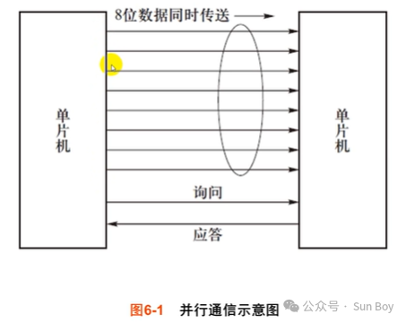
Parallel Communication and Serial Communication
Asynchronous and Synchronous Communication
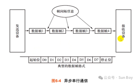
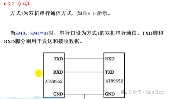
Asynchronous Serial Full Duplex (P3.0-RXD P3.1-TXD)
Timer 1 serves as the baud rate generator to control the rhythm of opening the door,
generating transmission and reception completion interrupts TI, RI
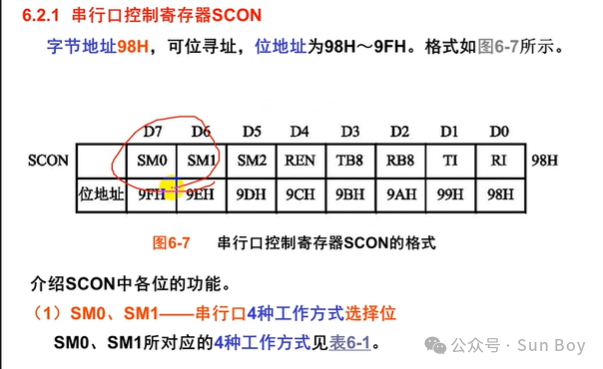
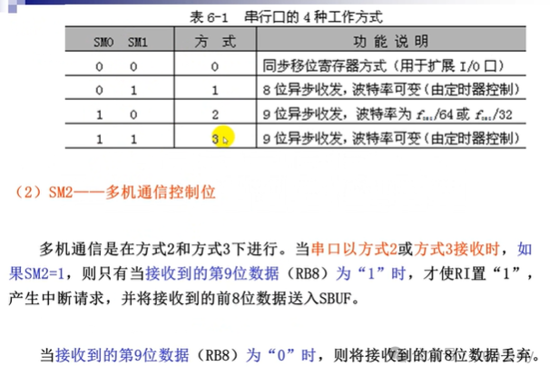
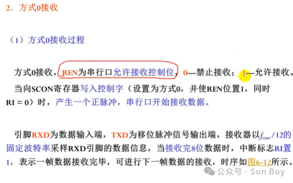
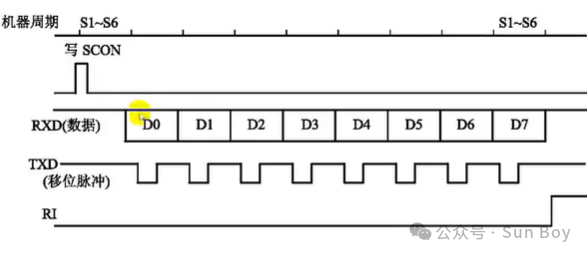
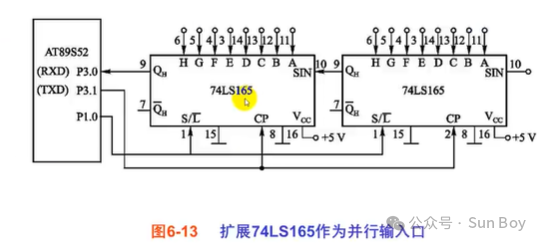
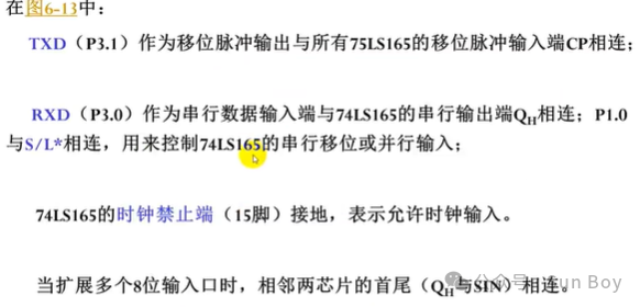
Mode 0 is used for expanding IO, while Modes 1-2 are communication modes.
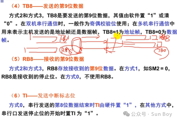
TB8 represents the stop bit for the data being sent, which is only useful during transmission, and is the RB8 of the receiver
RB8 is the stop bit for the received data, which is only useful during reception, and is the TB8 of the receiver
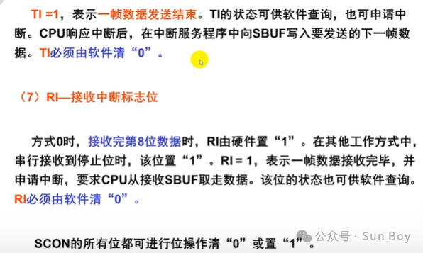
Serial port interrupts must be cleared by software
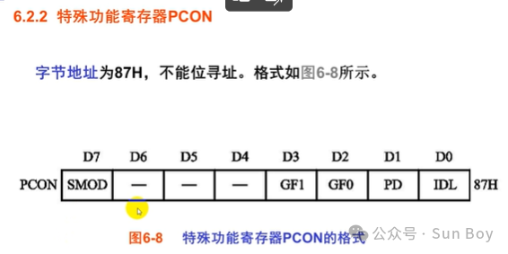
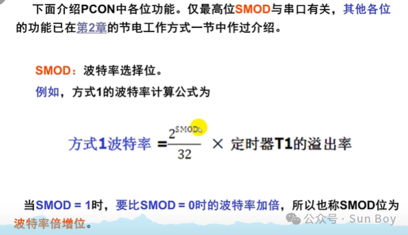
SMOD can be either 0 or 1
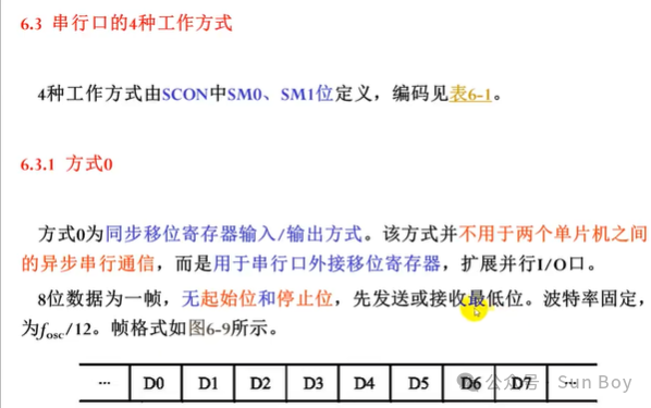
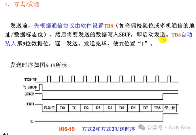
Low bits come first, high bits come later
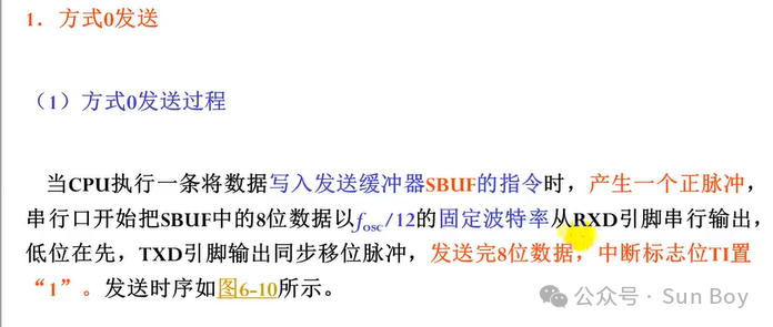
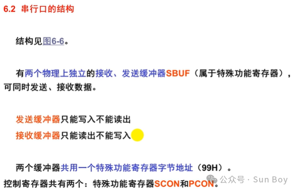
All are sent out, MOV SUBF, A. sends data out, the serial port opens automatically. MOV A. SUBF, receives data in, the serial port opens automatically

 All are received in, remember to configure scon
01

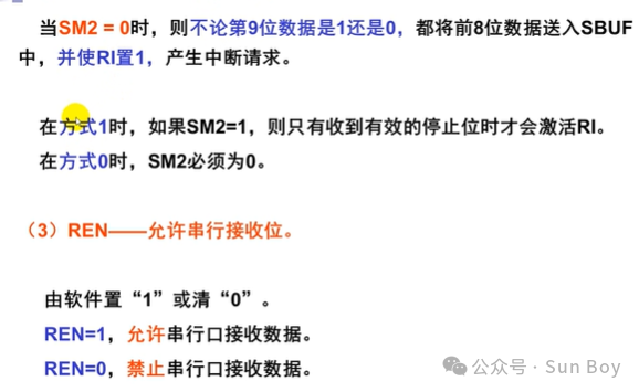
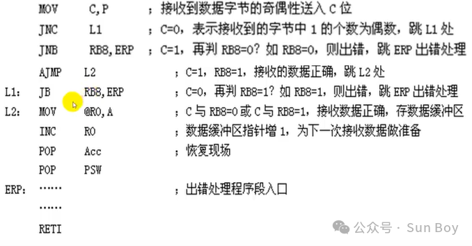
Valid reception conditions:

D8 stores the data sent from TB8, and the received D8 is stored in RB8
Key Point:
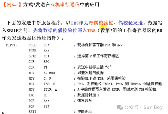
The second group R0 must set RS1=1, RS0=0.

Initialization has been completed earlier, this is just a demonstration of the interrupt program
P stores the parity of the data received as judged by the receiving microcontroller,
RB8 contains the ninth bit of the received data, which is written by the transmitter into the data to be sent in TB8
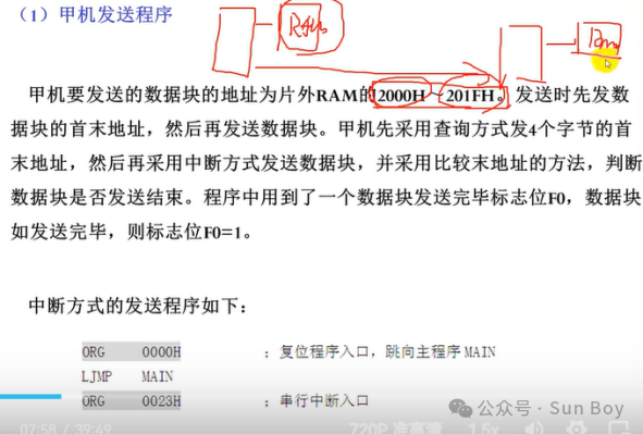
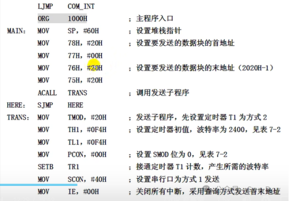
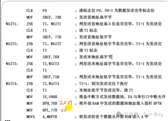
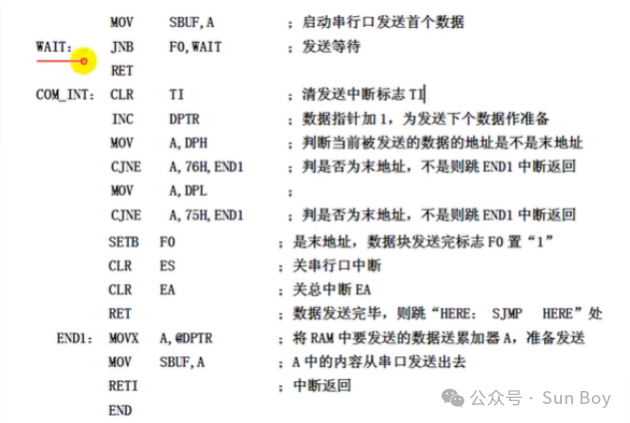
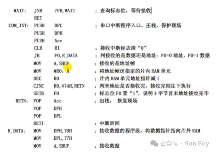
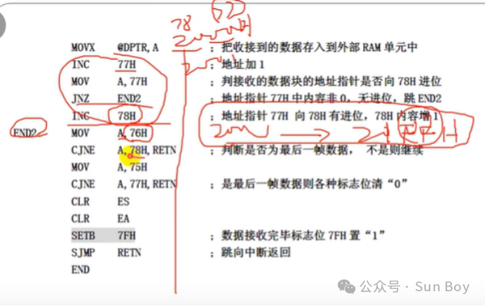
Example Problem: