This article mainly illustrates the specific application of the PROFIBUS-DP fieldbus in production sites through examples, detailing the hardware configuration, software programming, and relevant parameter settings for communication between Siemens PLC and frequency conversion devices via PROFIBUS-DP.
In industrial applications, especially in the steel metallurgy industry, it is most common to control frequency conversion devices using PLCs through the PROFIBUS-DP fieldbus to achieve the starting, stopping, and speed regulation of motors. Below, a specific example will describe the entire process of communication between the Siemens inverter and the S7-300/400 via PROFIBUS-DP.
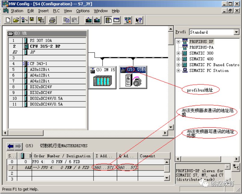
1. Hardware Configuration of the Inverter
In the STEP 7 software, create a project, then configure the hardware for this project, and establish a PROFIBUS-DP network. The inverter is configured in the PROFIBUS DP->SIMOVERT folder, and the communication address range is set. As shown in the figure below:
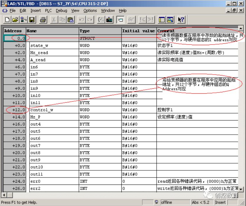
2. Establish Communication DB Block
Generally, the read and write data are done in a DB block, and it is best to divide the area of the DB block into the same size as the I/O address range set in the hardware configuration for easier correspondence and management. As shown in the figure below, the 12 bytes of data read from the inverter are in DB0 to DB11, and the 12 bytes of data written to the inverter are placed in DB12 to DB23. Next, other data such as communication error codes and additional calculation data related to the inverter can also be stored.
3. Write Communication Program
The communication program can directly call the system functions of the STEP 7 programming software
SFC14(DPRD_DAT), SFC15(DPWR_DAT) to implement. The example code segment is as follows:
CALL SFC 14 // Inverter -> PLC
LADDR :=W#16#230 // Communication address: the starting address of hardware configuration, i.e., in I Address 560
RET_VAL:=DB15.DBW24 // Error code: check help for specific meaning
RECORD :=P#DB15.DBX0.0 BYTE 12 // Transfer starting address and length
CALL SFC 15 // PLC -> Inverter
LADDR :=W#16#230 // Communication address: the starting address of hardware configuration, i.e., in Q Address 560
RECORD :=P#DB15.DBX12.0 BYTE 12 // Transfer starting address and length
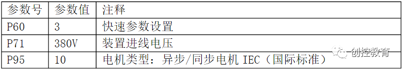
RET_VAL:=DB15.DBW26 // Error code: check help for specific meaning4. Inverter Parameter Settings
The simple parameter settings for the inverter are shown in the table below:
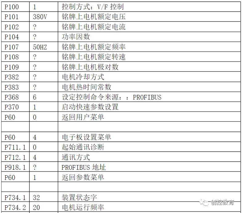
For writing data to the inverter, it establishes correspondence with the inverter’s k3001 to k3016 (refer to the inverter user manual function diagram 120). Reading data from the inverter corresponds to parameter P734. As shown in the figure below:
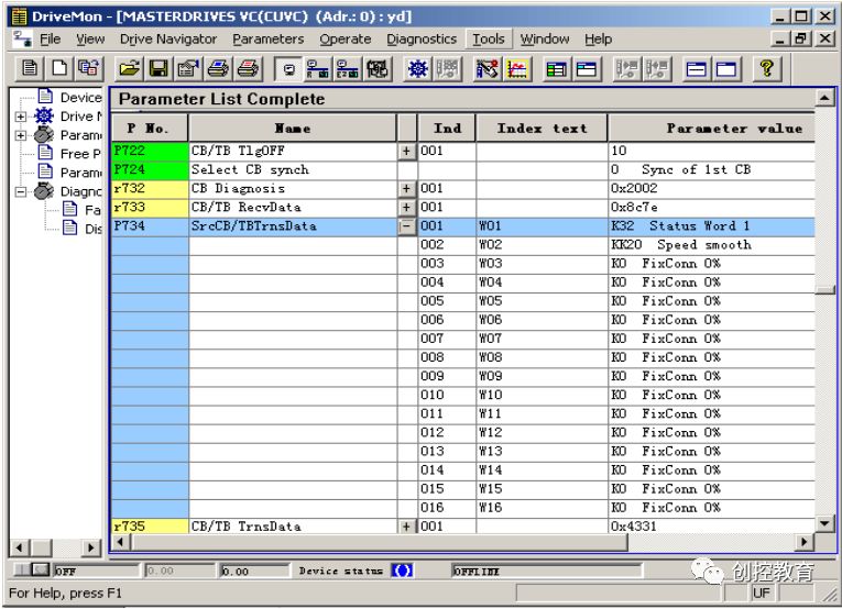
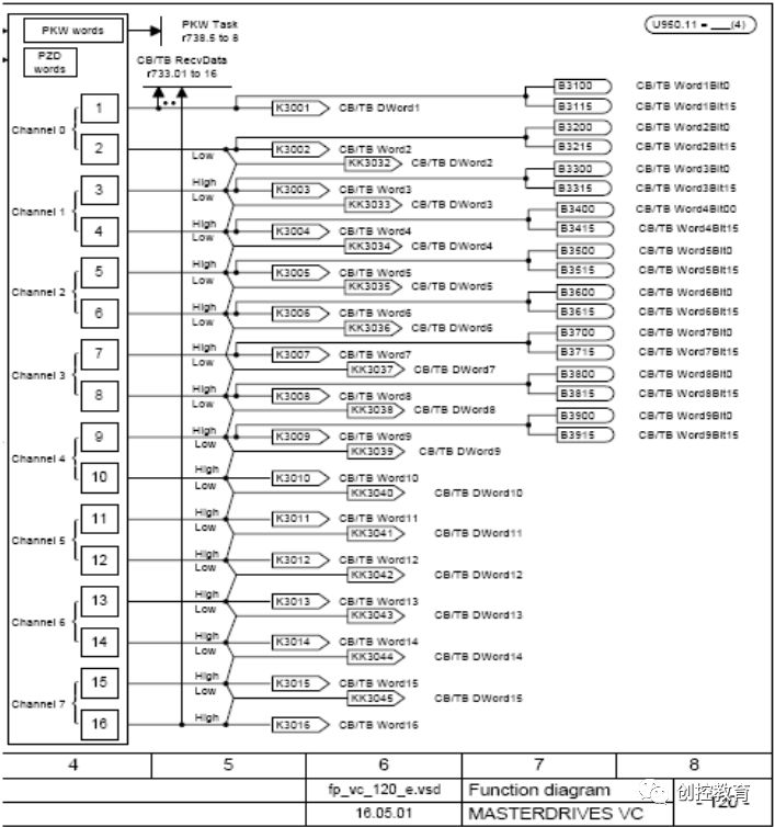
Thus, DB15.DBW12 to DB15.DBW22 correspond to P734’s W01 to W06. B15.DBW0 to DB15.DBW11 correspond to k3001 to k3012. PLC can read the inverter’s data by setting the value of parameter P734, and the data written to the inverter is stored in the inverter data k3001 to k3012, which can be called in the inverter’s parameter settings, thus establishing their correspondence.
In this way, the connection between the inverter and the PLC is basically established, and programs can be written to control the inverter’s start, stop, speed setting, and other functions through the PLC, meeting the process requirements. It is also possible to read the inverter data for display on the upper computer, achieving online monitoring and diagnosis.
-
(Content sourced from the internet, copyright belongs to the original author)
-
Disclaimer: If there are copyright issues, please contact for deletion!Neither individuals nor organizations bear relevant legal responsibilities.
-