Development of PROFIBUS DP data bus cable
WANG Hai-ling1, ZHANG Hong-yan2
(1. Anhui Xinke Cable Group Co., Ltd., Wuwei 238300, China; 2. Anhui Zongheng HI-TECH Cables Co., Ltd., Hefei 230051, China)
[Abstract]: With the continuous deepening and development of the domestic industrialization process, the demand for industrial automation networks is increasingly extensive. Especially since the release of GB/T20540-2006 PROFIBUS standard for industrial control systems in 2006, Profibus technology is widely used in manufacturing automation, process industry automation, and automation in buildings, traffic power, and other fields. However, there is no specification and standard for the data bus cable used for the connection of the PROFIBUS system, which brings inconvenience to the production and inspection of enterprises. This paper designs the cable structure with reference to the technical requirements of PROFIBUS DP data bus cable abroad, hoping to achieve the effect of throwing a brick to attract jade.
[Keywords]: PROFIBUS DP data bus cable; capacitance; impedance; attenuation; design
1. Introduction
With the continuous deepening and development of the domestic industrialization process, the demand for industrial automation networks is increasingly extensive. Traditional control methods can no longer meet the management and control needs of modern enterprises. Traditional control methods require fixed point-to-point connections of signals from field devices, including 24VDC or 0-20mA and various other signals. If the control equipment is not on-site, a large number of cables need to be laid to transmit various signals, which is labor-intensive and material-consuming. Moreover, once the system is expanded or modified, the entire cable must be changed and cannot keep pace with the changes in the structure of modern enterprise industrial automation systems. Profibus bus technology is a new technology formed to adapt to the intelligent, distributed, and networked development of automatic control systems. PROFIBUS fieldbus is an international, open, vendor-independent fieldbus standard. Due to the transmission speed of the PROFIBUS fieldbus being selectable in the range of 9.6kbit/s to 12Mbit/s, it has broad development prospects and advanced characteristics, widely used in manufacturing automation, process control automation, electricity, buildings, and transportation fields. Therefore, internationally renowned automation manufacturers have launched their respective fieldbus standards. For example, Germany released the DIN 19295 bus standard in 1959, Europe issued the EN 50170 bus standard in 1996, and the IEC International Electrotechnical Commission published the IEC61158 TYPE 3 Profibus standard in 1999. China’s Standardization Administration also released the GB/T20540-2006 standard in October 2006 (Measurement and Control Digital Data Communication Industrial Control System Fieldbus Type 3: PROFIBUS Specification). PROFIBUS consists of three compatible parts: PROFIBUS DP, PROFIBUS PA, and PROFIBUS FMS, among which PROFIBUS DP is a high-speed, low-cost communication used for device-level control systems and distributed I/O communication, which can replace 24VDC or 0-20mA signal transmission. However, there is no detailed introduction to the data bus cable for connecting PROFIBUS DP fieldbus devices, which brings difficulties in cable selection. This paper develops the cable based on the characteristics and transmission technical requirements of PROFIBUS DP fieldbus and briefly discusses cable material selection, structural design, and production control.
2. Main Technical Indicators and Design Focus
According to the performance requirements of PROFIBUS DP data bus cable from foreign companies, the main technical indicators of the cable are as follows:
(1) Characteristic Impedance
At 9.6 kHz, the cable characteristic impedance is (270±27%)Ω;
At 38.4 kHz, the cable characteristic impedance is (185±18.5%)Ω;
At 3-20 MHz, the cable characteristic impedance is (150±15%)Ω.
(2) Attenuation
At 9.6 kHz, the cable attenuation ≤0.25 dB/(100m);
At 38.4 kHz, the cable attenuation ≤0.40 dB/(100m);
At 4 MHz, the cable attenuation ≤2.2 dB/(100m);
At 16 MHz, the cable attenuation ≤4.2 dB/(100m).
(3) Working Capacitance
At 1 kHz, the cable capacitance ≤28.5 nF/km.
(4) Working Voltage
The maximum working voltage of the cable is 350 V.
(5) Conductor Resistance
The DC resistance of the conductor at 20°C should not exceed 55.0Ω/km;
(6) Insulation Resistance
The insulation resistance at 20°C should not be less than 10000Ω·km;
(7) Cable Working Environment Temperature
The cable working environment temperature is -40~70 ℃ (static).
(8) Cable Outer Diameter
The cable outer diameter is 8.0±0.4mm.
Through a comprehensive analysis of the performance requirements of PROFIBUS DP data bus cable, the above primary and secondary parameters are the key design focuses of the cable. In addition, the cable must also meet the requirements for high insulation resistance and low-temperature resistance. Based on the above design requirements, the key design focuses should be determined in terms of material selection, structural design, and production process control.
3. Material Selection and Process Control
(1) Conductor
The conductor is the key focus of the design of PROFIBUS DP data bus cable because it is an important carrier for signal transmission and one of the key factors affecting the primary and secondary parameters of the data bus cable. To reduce the working capacitance and attenuation of the cable, meet the requirements for the working environment temperature and outer diameter of the cable, and considering that the working frequency of the cable is not too high, oxygen-free copper wire is selected as the conductor of the data bus cable to meet the requirements.
According to the electrical performance index requirements of the cable, the conductor specification is selected as 22AWG, which is structured as 1×0.66 mm oxygen-free copper wire as the conductor. During production, the insulated core is manufactured by continuously drawing and annealing the conductor, preheating, and extruding the insulation in one go to ensure the uniform consistency of the insulated core structure and the stability of the cable’s electrical parameters, with the conductor diameter controlled within the range of 0.66±0.005 mm.
(2) Insulation
Insulation is the key to the design of PROFIBUS DP data bus cable, as the type of insulation has a crucial impact on signal transmission. It not only relates to the structure and working conditions of the cable but also determines the electrical characteristics of the cable, such as capacitance, attenuation, and characteristic impedance.
According to the usage conditions and electrical performance requirements of the PROFIBUS DP data bus cable, the insulation adopts a skin-foam-skin structure, with the inner skin being solid low-density polyethylene insulation material, which mainly enhances the insulation and adhesion of the conductor, improving the dielectric strength of the insulation. The foamed insulation layer is made of a mixture of low-density polyethylene, high-density polyethylene, and nucleating agents, which is physically foamed under the action of high-pressure, high-purity nitrogen during extrusion. The main role of the foamed insulation is to reduce the dielectric constant, working capacitance, and outer diameter of the cable. The outer skin is made of solid high-density polyethylene insulation material, which mainly increases the mechanical strength of the insulated single wire, protects the insulated core, and prevents moisture from entering the insulation and affecting the electrical performance of the cable. The polyethylene skin-foam-skin insulation structure is widely used in communication, radio frequency, and data bus cables with high performance requirements due to its low dielectric constant and dielectric loss characteristics, featuring a wide frequency range, low working capacitance, low attenuation, and high insulation properties, with a long-term allowable working temperature range of 55-70°C.
According to the performance index requirements of the PROFIBUS DP data bus cable for capacitance, characteristic impedance, attenuation, and outer diameter, the thickness of the inner skin insulation is controlled within the range of 0.10±0.02mm, the outer skin thickness is controlled within the range of 0.12±0.02mm, and the outer insulation is distinguished by red and green colors. The total outer diameter of the insulation is controlled within the range of 2.40-2.50mm. During production, considering the existence of insulation eccentricity, the outer diameter of the insulation is produced according to the upper deviation. The foaming degree of the insulation is controlled within the range of (60±5)%, and the eccentricity of the insulation does not exceed 5%.
(3) Cabling and Inner Sheath (if any)
The insulation of the PROFIBUS DP data bus cable is a skin-foam-skin structure, which has poorer compressive performance compared to solid polyethylene insulation. To prevent damage to the insulated core during cabling, which would affect the mechanical and electrical performance of the cable, the two insulated cores in red and green are twisted during cabling. The cabling direction is rightward, and the pitch is controlled within the range of 90-98 mm. During cabling, the tension of each core must be controlled well, and the pitch should be uniform to ensure the stability of the cable’s electrical performance. The cable core surface is wrapped with a polyester tape to prevent the insulated core from being burned during the subsequent inner sheath extrusion process.
Before shielding, according to customer requirements, a layer of soft white PVC material with a thickness of 0.40-0.50mm can be extruded as an inner sheath on the surface of the cable core to improve the roundness of the cable.
(4) Shielding
The shielding layer is wrapped with a 0.03mm thick aluminum-plastic composite tape, with a coverage rate of not less than 25%. Then, it is woven with a diameter of 0.12mm tinned copper wire, with a weaving density of not less than 80%. Double-layer shielding can improve the cable’s anti-interference performance, enhance the cable’s electromagnetic compatibility (EMC) capabilities, and reduce the radiation of external electromagnetic waves on the cable.
(5) Sheath
Although the cable is used for static installation, considering that the cable is in a -40°C low-temperature environment, the long-term bending installation of the cable may inevitably cause internal stress, leading to cracks or splits in the cable sheath. Therefore, to meet the usage environment requirements of -40 to 70°C, a low-temperature-resistant -40°C, high-temperature 70°C purple soft PVC material is used as the cable sheath. The sheath extrusion thickness is 0.7-0.8mm, and the cable outer diameter is controlled within the range of 8.00±0.4 mm.
4. Key Performance Design
According to the designed structure of the PROFIBUS DP data bus cable, as shown in Figure 1, the outer diameter of the conductor is 0.66mm, the outer diameter of the insulation is 2.40mm, and the outer diameter of the cable is 8.00±0.04 mm. The relevant electrical and transmission performance parameters of the cable are calculated to verify whether the performance design of the cable meets the design requirements.
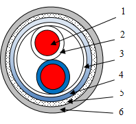
1- Bare copper conductor; 2- Skin-foam-skin insulation; 3- Polyester tape wrapping;
4- Aluminum-plastic composite tape; 5- Tinned copper wire woven shielding; 6- Purple PVC sheath.
Figure 1 Structure of PROFIBUS DP data bus cable
(1) Electrical Performance Design
The calculation formula for the effective resistance R of the cable conductor loop is:
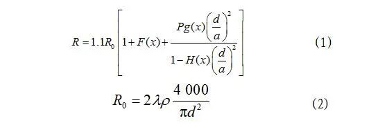
Where: R0 is the DC resistance of the conductor at 20°C, in Ω/km; λ is the twisting factor, taken as 1.02; ρ is the resistivity of pure copper wire conductor, taken as 0.017241 Ω·mm2/m; d is the conductor diameter, designed to be 0.66 mm; a is the distance between the centers of the symmetrical cable conductors, designed to be 2.40 mm; P is the correction factor for the twisted pair, taken as 1.0; F(x), g(x), H(x) are specific functions related to the materials and structure of the cable; x=kd/2, k is the eddy current coefficient, k=(ωμσ)1/2, where ω is the angular frequency, ω=2πf, f is the frequency, taken as 4 MHz, ω=2.512×10⁷ rad/s; μ is the magnetic permeability, μ=4π×107μr, μr is the relative magnetic permeability, taken as 1, μ=12.56×10⁷ H/m; σ is the conductivity, taken as 58.0 S·m/mm2. Through calculations, we can obtain R0=102.81 Ω/km, k=42.80, x=kd/2=14.124, F(x)=4.244, G(x)=2.372, H(x)=0.674, R=558.50 Ω/km.
The equivalent dielectric constant εD and the tangent of the equivalent dielectric loss angle tan δD of the cable insulation are calculated as follows:
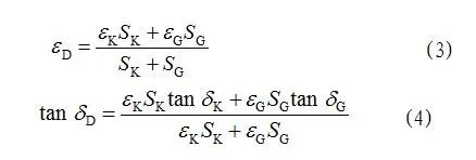
Where: εK is the relative dielectric constant of air, taken as 1; εG is the relative dielectric constant of the insulation, taken as 2.3; SK is the area occupied by air, designed to be 14.07 mm2; SG is the area occupied by insulation and filling, designed to be 4.00 mm2; tan δK is the tangent of the equivalent dielectric loss angle of air, taken as 0; tan δG is the tangent of the equivalent dielectric loss angle of the insulation, taken as 2.5×10⁻⁴. Through calculations, we can obtain εD=1.29, tan δD=9.89×10⁵.
The working capacitance C of the cable is calculated as:
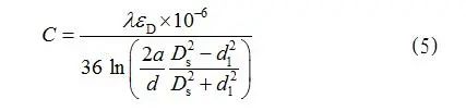
Where: λ=1.02; εD=1.29; a=2.40 mm; d=0.66 mm; Ds is the inner diameter of the shielding body, designed to be 4.95 mm; d1 is the outer diameter of the insulated core, designed to be 2.40 mm. Through calculations, we can obtain C=2.48×10⁸ F/km, meeting the design requirement of cable working capacitance ≤24.8 nF/km.
The inductance L of the cable is calculated as:
Where: λ=1.02; a=2.40 mm; d=0.66 mm; k=42.8; rs is the radius of the shielding body, designed to be 2.48 mm; Q(x) is a specific function related to the materials and structure of the cable, taken as 0.20; μr,s is the relative magnetic permeability of the shielding body, taken as 1. Through calculations, we can obtain L=6.32×10⁴ H/km.
The electrical conductivity G of the cable insulation is calculated as:

Where: ω=2.512×10⁷ rad/s, C=2.48×10⁸ F/km, tan δD=9.89×10⁵. Through calculations, we can obtain G=6.164×10⁵ S/km.
The characteristic impedance Z of the cable at 4 MHz is calculated as:
Where: L=6.32×10⁻⁴ H/km, C=2.48×10⁻⁸ F/km. Through calculations, we can obtain Z=159.6 Ω, meeting the design requirement of cable characteristic impedance (150±15)Ω.
(2) Transmission Performance Design
The attenuation constant α of the cable at 4 MHz is calculated as:
Where: R=558.50 Ω/km, G=6.164×10⁵ S/km, L=6.32×10⁴ H/km, C=2.48×10⁸ F/km. Through calculations, we can obtain α=15.2 dB/km=1.52 dB/(100 m), meeting the design requirement of cable attenuation constant ≤2.20 dB/(100 m).
By the same method, the characteristic impedance and attenuation at other frequencies are also calculated to meet the design requirements. The calculation results are as follows:
At 9.6 kHz, the calculated characteristic impedance is 271.9Ω; the attenuation value is 0.20 dB/(100 m);
At 38.4 kHz, the calculated characteristic impedance is 181.2Ω; the attenuation value is 0.26 dB/(100 m);
At 3-20 MHz, the calculated characteristic impedance is 158.5-160.1Ω;
At 4-16 MHz, the attenuation value is 1.52-3.01 dB/(100 m).
5. Performance Testing
According to the material selection, process control, and key performance design of the PROFIBUS DP data bus cable, the measured values are close to the theoretical calculated values, conforming to the technical specifications of PROFIBUS DP data bus cable, and meeting the usage requirements of the PROFIBUS data bus system. The specific test results of the PROFIBUS DP data bus cable are shown in Table 1. The cable meets the technical level of similar foreign products in terms of structural dimensions and electrical performance indicators.
6. Conclusion
The PROFIBUS DP data bus cable designed in this paper fully meets the technical requirements of similar foreign products in terms of structural dimensions and electrical performance indicators, satisfying the usage requirements of the PROFIBUS data bus. Through the detailed introduction of the PROFIBUS DP fieldbus cable, we have gained a deeper understanding of the structure and electrical performance parameters of the PROFIBUS DP fieldbus cable, providing a reference for the design and selection of PROFIBUS DP fieldbus cables in the future.
[References]
[1] Tang Zhiping. PROFIBUS Fieldbus Technology and Applications [J]. Journal of Changzhou Institute of Technology, 2000(12):26-29.
[2] Siemens, Lapp, etc. Company Fieldbus Cable Data.
[3] Zheng Yudong. Communication Cables [M]. Beijing: Mechanical Industry Press, 1982.