We use ADC2 to implement the potentiometer knob.
Potentiometer Knob Initialization Code.c
void PotentiometerKnob_Init(void){
/* Enable clock */
RCC_APB2PeriphClockCmd(RCC_APB2Periph_ADC2, ENABLE); // Enable ADC2 clock
RCC_APB2PeriphClockCmd(RCC_APB2Periph_GPIOA, ENABLE); // Enable GPIOA clock
/* Set ADC clock */
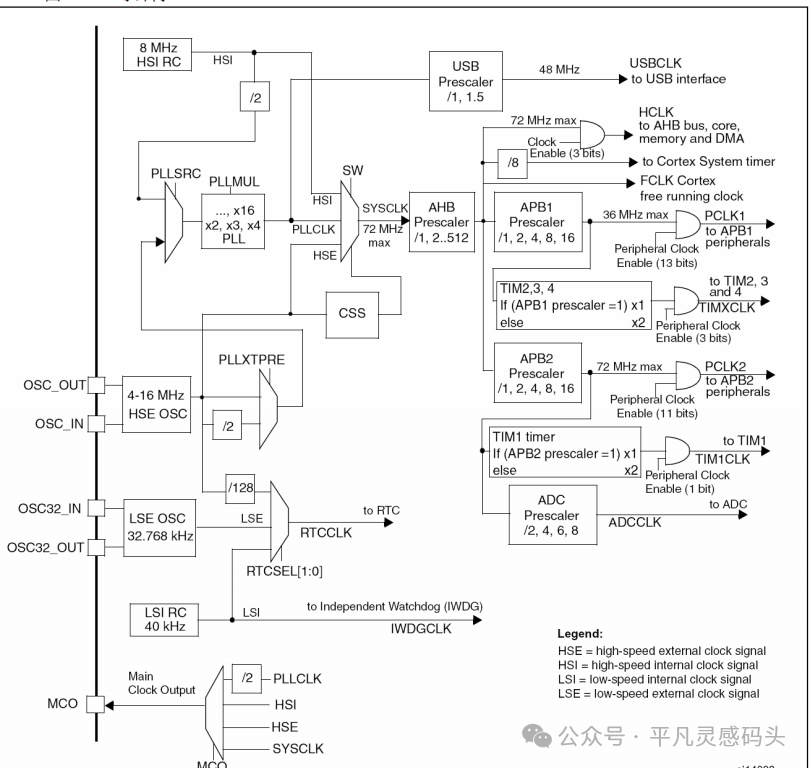
RCC_ADCCLKConfig(RCC_PCLK2_Div6); // Select clock division 6, ADCCLK = 72MHz / 6 = 12MHz
/* GPIO initialization */
GPIO_InitTypeDef GPIO_InitStructure;
GPIO_InitStructure.GPIO_Mode = GPIO_Mode_AIN;
GPIO_InitStructure.GPIO_Pin = GPIO_Pin_2 | GPIO_Pin_3 | GPIO_Pin_4 | GPIO_Pin_5;
GPIO_InitStructure.GPIO_Speed = GPIO_Speed_50MHz;
GPIO_Init(GPIOA, &GPIO_InitStructure); // Initialize PA2, PA3, PA4, PA5 as analog input
/* ADC initialization */
ADC_InitTypeDef ADC_InitStructure; // Define structure variable
ADC_InitStructure.ADC_Mode = ADC_Mode_Independent; // Mode, select independent mode, using ADC2 alone
ADC_InitStructure.ADC_DataAlign = ADC_DataAlign_Right; // Data alignment, select right alignment
ADC_InitStructure.ADC_ExternalTrigConv = ADC_ExternalTrigConv_None; // External trigger, use software trigger, no external trigger
ADC_InitStructure.ADC_ContinuousConvMode = DISABLE; // Continuous conversion, disabled, stop after one conversion
ADC_InitStructure.ADC_ScanConvMode = DISABLE; // Scan mode, disabled, only convert sequence 1
ADC_InitStructure.ADC_NbrOfChannel = 1; // Number of channels, 1, only needs to specify more than 1 in scan mode
ADC_Init(ADC2, &ADC_InitStructure); // Pass structure variable to ADC_Init, configure ADC2
/* Enable ADC */
ADC_Cmd(ADC2, ENABLE); // Enable ADC2, ADC starts running
/* ADC calibration */
ADC_ResetCalibration(ADC2); // Fixed process, internal circuit will automatically execute calibration
while (ADC_GetResetCalibrationStatus(ADC2) == SET);
ADC_StartCalibration(ADC2);
while (ADC_GetCalibrationStatus(ADC2) == SET);
}Overall Function Purpose
-
Open the clock for ADC2 and GPIOA;
-
Configure ADC2 clock to 12 MHz;
-
Configure GPIOA’s PA2, PA3, PA4, PA5 as analog input (ADC input pins);
-
Configure ADC2 parameters (operating mode, alignment, trigger mode, etc.);
-
Enable ADC2 and complete calibration.
Code Breakdown
1. Enable Clock
RCC_APB2PeriphClockCmd(RCC_APB2Periph_ADC2, ENABLE);  // Enable ADC2 clock
RCC_APB2PeriphClockCmd(RCC_APB2Periph_GPIOA, ENABLE);  // Enable GPIOA clock
-
Reason: In STM32, peripherals must have their clocks enabled before use, otherwise the registers will not work.
-
Here, the clocks for ADC2 and GPIOA are enabled.
2. Set ADC Clock
RCC_ADCCLKConfig(RCC_PCLK2_Div6); // ADC clock = 72 MHz / 6 = 12 MHz
-
The ADC clock in STM32 comes from the APB2 bus (PCLK2).
-
APB2 = 72 MHz, so dividing by 6 gives 12 MHz.
-
The maximum ADC clock for STM32F1 series cannot exceed 14 MHz.
3. GPIO Initialization (Analog Input)
GPIO_InitStructure.GPIO_Mode = GPIO_Mode_AIN;
GPIO_InitStructure.GPIO_Pin = GPIO_Pin_2 | GPIO_Pin_3 | GPIO_Pin_4 | GPIO_Pin_5;
GPIO_InitStructure.GPIO_Speed = GPIO_Speed_50MHz;
GPIO_Init(GPIOA, &GPIO_InitStructure);
-
Configure PA2, PA3, PA4, PA5 as analog input.
-
<span>GPIO_Mode_AIN</span>= analog input, indicating these pins are directly connected to the ADC, bypassing digital circuits. -
<span>GPIO_Speed</span>has no effect in analog mode but must be specified.
4. ADC Parameter Initialization
ADC_InitStructure.ADC_Mode = ADC_Mode_Independent;
ADC_InitStructure.ADC_DataAlign = ADC_DataAlign_Right;
ADC_InitStructure.ADC_ExternalTrigConv = ADC_ExternalTrigConv_None;
ADC_InitStructure.ADC_ContinuousConvMode = DISABLE;
ADC_InitStructure.ADC_ScanConvMode = DISABLE;
ADC_InitStructure.ADC_NbrOfChannel = 1;
ADC_Init(ADC2, &ADC_InitStructure);
-
Independent Mode (ADC_Mode_Independent) STM32 has ADC1, ADC2 (some models also have ADC3), which can sample in dual mode; here only ADC2 is used, selecting independent mode.
-
Data Alignment (ADC_DataAlign_Right) The ADC result is 12 bits, right alignment means the lower 12 bits are valid, and the upper 4 bits are filled with 0.
-
Trigger Mode (ADC_ExternalTrigConv_None) No external trigger is used; it is started by software.
-
Continuous Conversion Mode (ADC_ContinuousConvMode) Disabled, meaning only one sample is taken, then it stops.
-
Scan Mode (ADC_ScanConvMode) Disabled, meaning only one channel is sampled. If multiple channels need to be sampled sequentially, scan mode must be enabled, and
<span>ADC_NbrOfChannel > 1</span>must be set. -
Number of Channels (ADC_NbrOfChannel = 1) Only one channel is configured, corresponding to non-scan mode.
5. Enable ADC
ADC_Cmd(ADC2, ENABLE);
-
Enable ADC2 to allow it to operate.
6. ADC Calibration
ADC_ResetCalibration(ADC2);  // Reset calibration register
while (ADC_GetResetCalibrationStatus(ADC2) == SET);
ADC_StartCalibration(ADC2);  // Start calibration
while (ADC_GetCalibrationStatus(ADC2) == SET);
-
Why calibrate? The ADC has analog circuits that may deviate due to temperature and power supply. STM32 provides an internal calibration function that automatically adjusts the offset to improve accuracy.
-
Fixed process:
-
Reset the calibration register first;
-
Wait for the reset to complete;
-
Start calibration;
-
Wait for calibration to complete.
Please refer to the ADC Basics Study
HS, WeChat public account: Ordinary Inspiration Dock STM32F4xx ADC Conversion
Get the AD value function of the potentiometer knob.c
* Parameter: n specifies the potentiometer knob, range: 1~4, representing RP1, RP2, RP3, RP4 respectively
* Return value: AD conversion value, range: 0~4095
uint16_t RP_GetValue(uint8_t n){
	if (n == 1)  // Specify to read RP1
	{
		/* Configure the regular group for channel 2 (PA2) */
		ADC_RegularChannelConfig(ADC2, ADC_Channel_2, 1, ADC_SampleTime_55Cycles5);
	}
	else if (n == 2)  // Specify to read RP2
	{
		/* Configure the regular group for channel 3 (PA3) */
		ADC_RegularChannelConfig(ADC2, ADC_Channel_3, 1, ADC_SampleTime_55Cycles5);
	}
	else if (n == 3)  // Specify to read RP3
	{
		/* Configure the regular group for channel 4 (PA4) */
		ADC_RegularChannelConfig(ADC2, ADC_Channel_4, 1, ADC_SampleTime_55Cycles5);
	}
	else if (n == 4)  // Specify to read RP4
	{
		/* Configure the regular group for channel 5 (PA5) */
		ADC_RegularChannelConfig(ADC2, ADC_Channel_5, 1, ADC_SampleTime_55Cycles5);
	}
	ADC_SoftwareStartConvCmd(ADC2, ENABLE);  // Software trigger AD conversion once
	while (ADC_GetFlagStatus(ADC2, ADC_FLAG_EOC) == RESET);  // Wait for EOC flag, i.e., wait for AD conversion to complete
	return ADC_GetConversionValue(ADC2);  // Read data register to get AD conversion result
}
Function Purpose
uint16_t RP_GetValue(uint8_t n)
-
Input parameter
<span>n</span>: indicates which channel to read (1~4). -
Return value: returns the ADC conversion result (range 0~4095, 12-bit ADC).
2. Select Channel
if (n == 1) // Read RP1
{
	ADC_RegularChannelConfig(ADC2, ADC_Channel_2, 1, ADC_SampleTime_55Cycles5);
}
else if (n == 2) // Read RP2
{
	ADC_RegularChannelConfig(ADC2, ADC_Channel_3, 1, ADC_SampleTime_55Cycles5);
}
else if (n == 3) // Read RP3
{
	ADC_RegularChannelConfig(ADC2, ADC_Channel_4, 1, ADC_SampleTime_55Cycles5);
}
else if (n == 4) // Read RP4
{
	ADC_RegularChannelConfig(ADC2, ADC_Channel_5, 1, ADC_SampleTime_55Cycles5);
}
Here, the function is used:
ADC_RegularChannelConfig(ADC_TypeDef* ADCx, uint8_t ADC_Channel, uint8_t Rank, uint8_t SampleTime);
Parameter description:
-
<span>ADC2</span>: Select ADC2. -
<span>ADC_Channel_x</span>: Specify ADC channel (PA2=Channel_2, PA3=Channel_3, PA4=Channel_4, PA5=Channel_5). -
<span>Rank=1</span>: Specify as the first in the regular sequence (since scan mode is not enabled, there is only one). -
<span>SampleTime=55Cycles5</span>: Sample time, indicating that the ADC holds the sample for 55.5 cycles.
3. Software Trigger One Conversion
ADC_SoftwareStartConvCmd(ADC2, ENABLE);
-
Start one regular group conversion (software trigger mode).
-
Since it was configured during initialization as
<span>ADC_ExternalTrigConv = None</span>, it must be started by software.
4. Wait for Conversion to Complete
while (ADC_GetFlagStatus(ADC2, ADC_FLAG_EOC) == RESET);
-
<span>EOC</span>= End Of Conversion (conversion complete flag). -
The code will block here until the conversion is complete.
5. Read Result
return ADC_GetConversionValue(ADC2);
-
Return the converted digital value (0~4095).
-
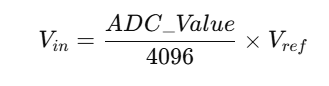
Relationship between digital value and voltage:
-
Where
<span>Vref</span>is typically 3.3V.
For example: If the sampling result = 2048, it indicates the input voltage is approximately:
