01
What is Arduino
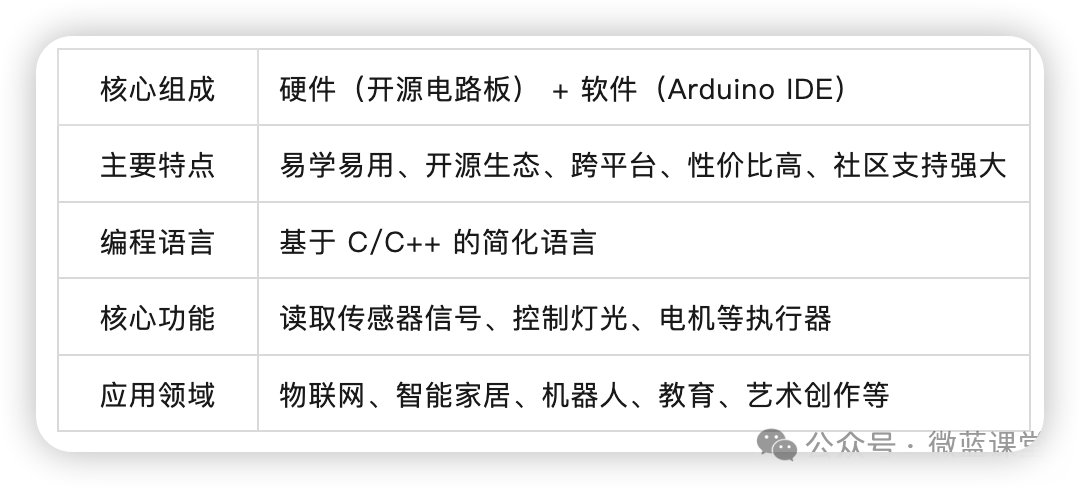
Arduino is a convenient, flexible, and easy-to-use open-source electronic prototyping platform. It consists of hardware (various models of Arduino boards) and software (Arduino IDE), originally intended to make it easier for artists, designers, hobbyists, and anyone interested in creating interactive objects to use electronic technology.
02
The Origin of Arduino
In the winter of 2005, in a small town called Ivrea in northern Italy, there was a school known as the Ivrea Interaction Design Institute.
Massimo Banzi, a teacher at this school, often heard complaints from his students about the lack of a microcontroller that was both affordable and easy to use. At that time, the most commonly used controller was called the BASIC Stamp, which cost as much as $100 and was very difficult to use, making it unfriendly for students who were not majoring in electronics.
At this time, a Spanish chip engineer named David Cuartielles visited their school. Banzi explained the problem to him, and after some discussion, they decided to design a new circuit board, bringing Banzi’s student David Mellis on board to design a programming language for the circuit board.
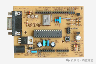
Two days later, Mellis completed the development of the programming language, and three days later, the circuit board was finished, leading to the birth of the first-generation Arduino.
03
The Origin of the Name Arduino
Arduin was a count from Ivrea who became king in 1002 but was deposed by King Henry II of Germany just two years later. A bar in the town of Ivrea named itself di Re Arduino in honor of this king. Massimo Banzi liked to visit this bar, so he named the circuit board Arduino, which in Italian means strong friend.
04
The Philosophy of Arduino
4.1 Open Source Sharing
Both hardware and software are completely open source, allowing anyone to freely use, modify, distribute, or even sell designs based on Arduino, as long as they follow the same open-source protocol and retain the original contributors’ attribution.
4.2 Simple and Easy to Use
Arduino is dedicated to lowering the technical barrier, enabling more people to engage with and create electronic projects. Through expansion boards and a rich variety of sensor/actuator modules, users can quickly build complex systems like “building blocks” without needing to deeply understand the underlying hardware connections.
4.3 Community Collaboration
The open-source model encourages developers worldwide to inspect, improve code and designs, and share their projects and libraries. This collective intelligence allows the Arduino ecosystem to quickly respond to diverse needs, spawning a large number of compatible hardware, expansion modules, and innovative projects, forming a healthy ecosystem of “commercial and open-source symbiosis”.
05
The Evolution of Arduino
First Generation: Arduino Severino
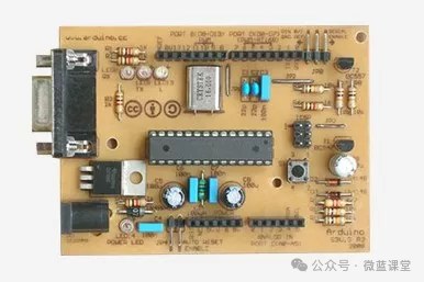
Made with single-sided PCB, all components are through-hole packages. Although this version appears somewhat rough by today’s aesthetic standards, it established the core framework of Arduino: pin sockets distributed on both sides, programs downloaded via serial port and Arduino Bootloader; the control board is equipped with a physical reset button, a dedicated external power supply interface for high-power devices, and an LED connected to Pin-13—allowing beginners to run the “Blink” example code without any external devices, setting the tone for Arduino’s subsequent development.
Second Generation: Arduino Serial
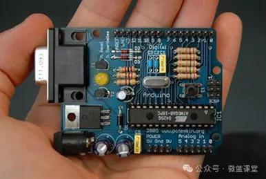
Utilizing a double-sided PCB with blue solder mask, this generation significantly improved aesthetics compared to its predecessor. Additionally, this product adopted a new cutting shape and mounting hole positions, a design that continues to this day, establishing the identification features of the “main product line” and being the first product used by the Arduino team for promotion and market entry.
Third Generation: Arduino Extreme
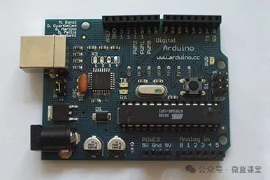
Integrated with a USB serial converter module, this improvement was significant for beginners using laptops, allowing them to operate the Arduino control board directly without needing to purchase a separate converter, greatly lowering the usage barrier. Meanwhile, this version replaced most components with surface-mounted devices, which was highly beneficial for mass production, effectively improving production efficiency and product consistency.
Fourth Generation: Arduino NG
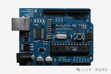
Improved the serial chip and restored the “L13” onboard LED design that was missing in the subsequent two generations after changing the PCB process.
Fifth Generation: Arduino Diecimila
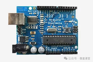
Added a software reset function, allowing users to see the execution effect of the program without manually pressing the reset button after downloading the program. This generation also included a fuse to prevent high-power components connected by users from burning out the computer’s USB interface or even the motherboard.
Sixth Generation: Arduino Duemilanove
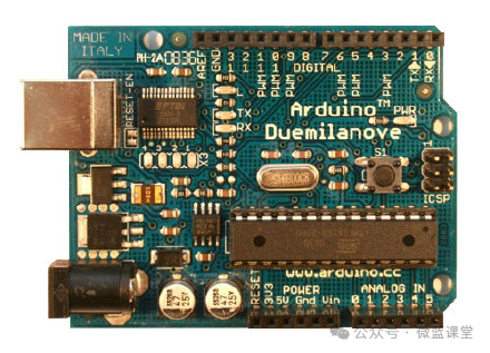
Replaced with a more advanced 328p chip, allowing users to run larger programs, operate more sensors, and handle more complex components. Arduino began to focus on user experience.
Seventh Generation: Arduino UNO
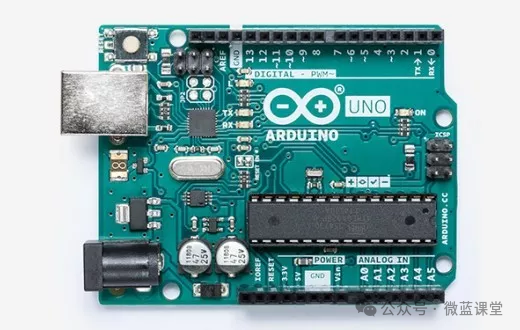
The USB interface chip uses the ATmega16U2, transforming the UNO’s USB interface from a simple “converter bridge” into a programmable, intelligent co-processor, providing the hardware basis for simulating keyboard, mouse, game joystick, and other USB HID device functions.
The main control chip is the ATmega328P, offering more uniform and stable performance.
Continues to support automatic power switching functionality, further optimizing this part of the circuit design for more stable and reliable power supply.
06
The Product Hierarchy of Arduino
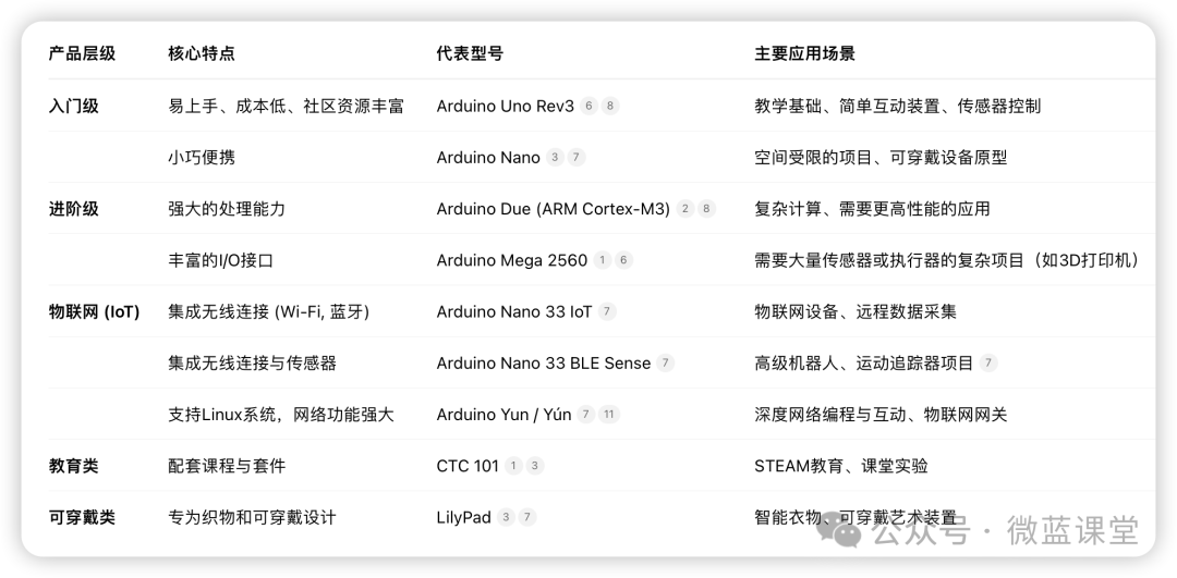
Nano Series
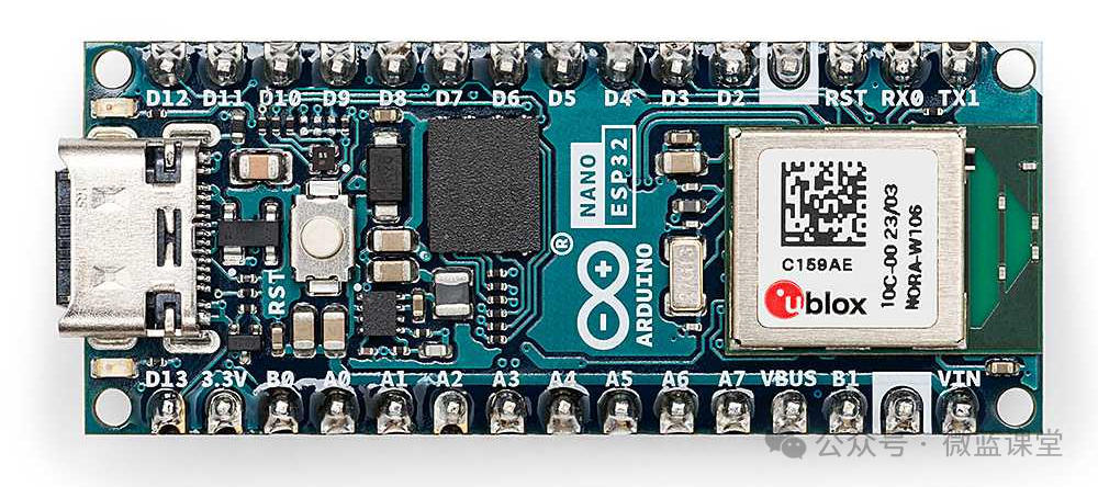
The Nano series is a set of compact yet feature-rich development boards. This series ranges from the economical basic model Nano Every to the fully-featured Nano 33 BLE Sense / Nano RP2040 Connect, which integrates Bluetooth®/Wi-Fi® wireless modules. These boards also come with a variety of embedded sensors, such as temperature and humidity, pressure, gesture, and microphone. They support programming in MicroPython and also feature machine learning capabilities.
MKR Series
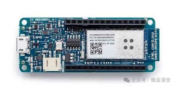
The Arduino MKR series is a modular product line consisting of development boards, expansion boards, and carrier boards, allowing for various innovative projects without additional circuitry. Each development board in this series (except for the MKR Zero) is equipped with a wireless communication module, supporting multiple communication protocols such as Wi-Fi®, Bluetooth®, LoRa®, Sigfox®, and NB-IoT. All boards are based on the Arm® Cortex®-M0 32-bit SAMD21 low-power processor and include encryption chips to ensure secure communication.
Classic Series
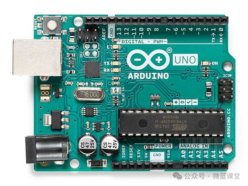
The Arduino Classic family is a long-standing and highly regarded series of development boards in the Arduino ecosystem, known for their stability, ease of use, and strong community support, making them the foundation for many electronic projects and educational practices. This family mainly includes classic models such as Arduino UNO, Leonardo, and Micro, all based on 8-bit AVR architecture microcontrollers, maintaining excellent compatibility with the traditional Arduino IDE and a large number of expansion boards (Shields).
Mega Series
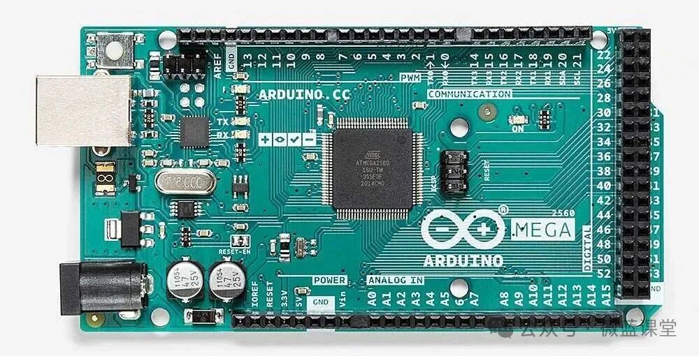
The Mega series is designed for projects that require powerful computing capabilities and a large number of GPIO pins. This series is represented by the Arduino Mega 2560, which is powered by the ATmega2560 microcontroller, providing 54 digital I/O pins (15 of which can be used for PWM output) and 16 analog input pins, along with 256KB of flash memory and 8KB of SRAM, making it ideal for handling complex tasks and connecting numerous sensors and actuators.
07
UNO MOC Driver
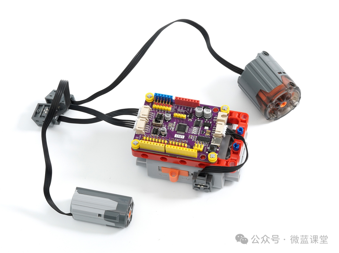
Finally, let me introduce a very practical Arduino development board: compatible with LEGO small particle blocks, built-in 2 LEGO motor drivers, and supports power supply from LEGO battery boxes.
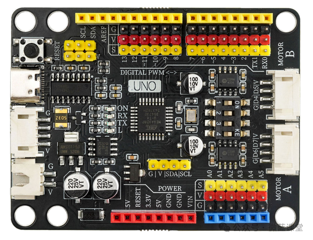
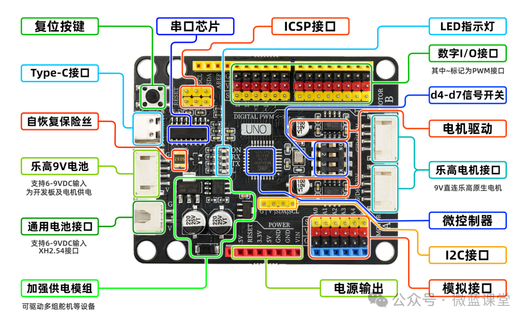
- ① Reset ButtonPress the reset button to rerun the program.
- ② USB Serial ChipThis chip is responsible for converting data received via USB into serial data for the main control chip.
- ③ 5V/1A Power ModuleThe power module provides power services for the main board, stabilizing the external 6-12V power supply to 5V/2A/10W output, capable of driving multiple servos, toy motors, micro slides, and other devices.
- ④ PH2.0 4P Power Interface (Compatible with LEGO Battery Box)This interface is compatible with the LEGO battery box wiring protocol, allowing connection with the LEGO battery box using the matching power adapter cable. The output voltage of this interface is 6-9V, depending on your input voltage.
- ⑤ USB InterfaceUSB Type-C interface, responsible for data downloading and USB power supply.
- ⑥ 3.3V Power ChipProvides 3.3V voltage output for the development board.
- ⑦ External Power and USB Power Automatic Switching ControllerThe external power and USB power automatic switching system consists of FDN340P MOSFET and LMV358IDGKR amplifier. The development board is powered by the USB interface by default, and when an external power supply is connected, the controller automatically disconnects the USB power and switches to external power supply. When the external power is disconnected, it automatically switches back to USB power, protecting the computer from power interference from the development board.
- ⑧ Self-resetting FuseWhen a short circuit occurs due to incorrect connections, the fuse automatically disconnects the circuit between the development board and the computer, protecting the computer’s USB interface from being burned out or freezing.
- ⑨ Digital G|V|S Expansion InterfaceThe onboard digital G|V|S interface makes it more convenient to connect sensors or actuators, eliminating the need for expansion boards when building projects. G is the GND power negative, V is the VCC power positive, and S is the IO signal interface, providing 5V/2A output power to meet the power needs of most sensors and actuators.
- ⑩ Analog G|V|S Expansion InterfaceThe onboard analog G|V|S expansion interface makes it more convenient to connect analog sensors, with new A6 and A7 analog input interfaces for connecting more sensors.
- ⑪ ICSP Serial Data InterfaceConnect to this interface to write initialization programs or download programs using the compiler.
- ⑫ ATMEGA328P Main Control ChipThe ATMEGA328P main control chip is the brain of the development board, responsible for program storage, execution, computation, and signal input/output functions.
- ⑬ Crystal OscillatorProvides clock signals for the ATMEGA328P main control chip.
- ⑭ LED Indicator LightsThere are 4 onboard LED indicator lights, (ON) is the power indicator light, which lights up when powered on, (RX)(TX) are serial signal indicator lights that flash when there is serial signal communication, and (L) is the D13 pin light, which lights up when the D13 signal is High.
- ⑮Motor, Motor Driver Chip, and Driver SwitchTwo driver chips are onboard, outputting power of 9V | 2A, supporting PWM speed regulation. A toggle switch is provided to control whether the motor driver is operational.
- ⑯Motor, Motor InterfaceThe motor interface uses a PH2.0 4P terminal interface, compatible with LEGO motor wiring, allowing direct connection to LEGO motors using the included adapter cable.
- ⑰XH2.54 Power InterfaceThis interface is mainly used to connect lithium battery power supply, with an input voltage of 6-9V.
- ⑱LEGO Block Mounting HolesThe mounting hole diameter is 4.7mm, fully compatible with LEGO blocks.
Students needing accessories can purchase them from my Taobao store under the same name.
 Follow me for more sharing|Weilan Classroom