PCB-Level Thermal Design (Part 1)
All electronic products contain semiconductor devices, capacitors, and other components that are susceptible to thermal acceleration failure mechanisms. Thermal design is crucial for improving the reliability of any design. However, thermal design can be very challenging due to the complex geometries involved in fluid dynamics mathematical analysis. Below, we will explain how to conduct thermal design from an engineering perspective.
Thermal Resistance
First, let us explain the definition of thermal resistance. Thermal resistance is an indicator of how easily heat is conducted. Represented graphically and mathematically, thermal resistance is defined as the temperature difference between two points divided by the heat flow (power dissipation) P between those two points, as shown in the figure: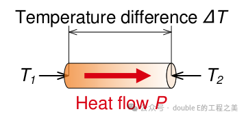
Define thermal resistance as Θ:
Below is a typical switching power supply chip soldered onto a 4-layer 1.6mm PCB.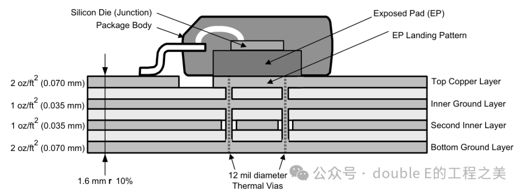
The chip datasheet will define some common thermal parameters, calculated as follows:
With these parameters, we can estimate whether the operating temperature of the device meets the actual working conditions.
Thermal Conductivity and Heat Transfer Coefficient
Thermal conductivity 𝑘 is the ability of a material to conduct heat per unit length and per unit temperature difference, measuring the strength of heat transfer within the material, with units, calculated using the formula:
Where:𝑞: Heat flow (W)𝑘: Thermal conductivity (W/m·K)𝐴: Cross-sectional area (m²)Δ𝑇: Temperature difference (K or °C)Δ𝑥: Thickness (m)Common materials’ thermal conductivity coefficients:
| Material | |
| Copper | 390 |
| Aluminum | 237 |
| Stainless Steel | 16 |
| Air | 0.025 |
The heat transfer coefficient ℎ (also known as the convective heat transfer coefficient) describes the ability of heat transfer between a solid surface and a fluid through convection or radiation, with units
Where:𝑞: Heat flow (W)ℎ: Heat transfer coefficient (W/m²·K)𝐴: Heat transfer area (m²)Δ𝑇: Temperature difference between the solid surface and the fluid (K or °C)Typical heat transfer coefficients in various scenarios:
| Scenario | |
| Natural Convection Air | 5 ~ 25 |
| Forced Convection Air | 25 ~ 250 |
| Water (Forced Flow) | 500 ~ 10,000 |
| Boiling Water | 2,500 ~ 100,000 |
Other Related Material Thermal Resistances
Copper Thermal Resistance
For a copper piece with dimensions of 1cm x 1cm and a thickness of 1 ounce (0.0035mm), with a thermal conductivity of, calculate the thermal resistance of copper:
Thermal Resistance of Vias
For a via with a length of 0.165cm (65mils), copper thickness of 0.5 ounces (0.00175mm), and a radius of 6mil (0.01524 cm), with a thermal conductivity of, calculate the thermal resistance of the via:
Result:
Thermal Resistance from PCB to Air
For a PCB with dimensions of 1cm x 1cm, assuming a natural convection air heat transfer coefficient of 0.001W/(cm²·℃), the calculation yields:
Thermal Resistance of PCB Material
For a PCB with dimensions of 1cm x 1cm, made of FR4 material with a thickness of 0.032cm (12.6mil), with a thermal conductivity of, the calculation yields:
The above constitutes the thermal resistance model at the PCB level, allowing estimation of PCB material, via size and quantity, copper thickness, PCB dimensions, and whether additional passive cooling measures are needed for the chip.
Engineering Calculations
Below is the thermal parameter table for the TI switching power supply chip LMR33630.
| Thermal Resistance | Description | Unit |
| Junction-to-ambient thermal resistance | 72.5°C/W | |
| Junction-to-case (top) thermal resistance | 35.9°C/W | |
| Junction-to-board thermal resistance | 23.3°C/W | |
| Junction-to-top characterization parameter | 0.8°C/W | |
| Junction-to-board characterization parameter | 23.5°C/W | |
| Junction-to-case (bottom) thermal resistance | N/A°C/W | |
| Junction temperature | 150°C |
For example:The DCDC power chip LMR33630 operates at an ambient temperature of 85 degrees Celsius, with a power output of 3.3V3A and an efficiency of 90%. Can the power supply operate normally at this temperature?Given conditions:, calculate:
The calculated junction temperature of the chip will exceed the junction temperature under these conditions, necessitating additional cooling measures.