
PCB design is based on the circuit schematic to achieve the functions required by the circuit designer. This article summarizes several common issues in PCB circuit design for reference, hoping that engineers can continuously improve in their circuit designs, achieving excellent circuit performance and heat dissipation, effectively saving production costs.
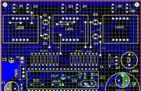
1. Overlapping Pads
1. The overlap of pads (except for surface mount pads) means overlapping holes, which can lead to broken drill bits and damage to the holes during the drilling process due to multiple drillings at one location.
2. In multilayer boards, if two holes overlap, such as one hole being an isolation pad and the other being a connection pad (via pad), the resulting film will show as an isolation pad, leading to scrap.
2. Misuse of Graphic Layers
1. Some useless connections are made on graphic layers, leading to confusion by designing more than five layers for a four-layer board.
2. For convenience, designers may use the Board layer to draw lines that exist on all layers, and also use the Board layer for annotation lines. This can lead to missing connections during photoplotting data if the Board layer is not selected, or short circuits if the annotation lines on the Board layer are selected. Therefore, it is important to maintain the integrity and clarity of graphic layers during design.
3. Violating conventional design practices, such as designing component faces on the Bottom layer and soldering faces on the Top layer, causes inconvenience.
3. Misplacement of Characters
1. Characters covering SMD pads can complicate continuity testing and component soldering on the printed circuit board.
2. Characters that are too small can make screen printing difficult, while those that are too large can overlap, making them hard to distinguish.
4. Setting the Hole Diameter for Single-Sided Pads
1. Single-sided pads generally do not have holes drilled; if holes are necessary, they should be marked with a diameter of zero. If a value is designed, coordinates for the hole will appear in the drilling data, leading to issues.
2. If a hole is drilled in a single-sided pad, it should be specially marked.
5. Using Fill Blocks to Draw Pads
Using fill blocks to draw pads can pass DRC checks during design, but it is not suitable for processing. Therefore, such pads cannot directly generate solder mask data, and when applying solder mask, the area of the fill block will be covered, making component soldering difficult.
6. Power and Ground Layers as Via Pads and Connections
Designing power and ground layers as via pads can lead to the actual printed circuit board image being opposite to the intended design, with all connections being isolation lines. Designers should be very clear about this. Additionally, when drawing several groups of power or ground isolation lines, care should be taken to avoid leaving gaps that could short-circuit two power groups or block the connection area (separating one power group).
7. Unclear Definition of Processing Layers
1. For single-sided board designs on the TOP layer, if not specified for front and back, the produced board may have difficulty soldering components.
2. For example, a four-layer board designed with TOP, mid1, mid2, and bottom layers may not be processed in that order, which requires clarification.
8. Excessive Use of Fill Blocks or Using Very Thin Lines for Filling
1. This can lead to loss of photoplotting data, resulting in incomplete data.
2. Since fill blocks are drawn line by line during photoplotting data processing, the resulting data volume is quite large, increasing the difficulty of data processing.
9. Pads for Surface Mount Devices Too Short
This is a concern for continuity testing; for densely packed surface mount devices, the distance between their pins is quite small, and the pads are also quite thin. When installing test probes, they must be staggered vertically (or horizontally). If the pads are designed too short, although it does not affect component installation, it will make it difficult to position the test probes.
10. Small Spacing in Large Area Grids
The edges between lines in large area grids should not be too small (less than 0.3mm). During the PCB manufacturing process, after exposure, many small film fragments can adhere to the board, causing broken lines.
11. Large Area Copper Foil Too Close to the Outer Frame
Large area copper foil should maintain a distance of at least 0.2mm from the outer frame, as milling the shape can easily lead to copper foil warping and subsequent solder mask peeling issues.
12. Unclear Design of the Outer Frame
Some clients design outline lines in the Keep layer, Board layer, Top over layer, etc., and these outline lines do not overlap, making it difficult for PCB manufacturers to determine which outline line to follow.
13. Uneven Graphic Design
This can lead to uneven plating during graphic electroplating, affecting quality.
14. Use Grid Lines for Large Copper Areas to Avoid Blistering During SMT


Screenshots from Some Electronic Books

【Complete Set of Hardware Learning Materials Collection】