Follow+Star Public Account, Don’t Miss Exciting Content
Source Material | Network
OTA upgrades are no longer a novelty; most IoT terminal devices now have this capability.
Today, we will share the detailed process of OTA upgrades using the AT32 as an example.
The OTA (Over-the-Air Technology) allows users to write to specific areas of User Flash during program execution, facilitating firmware updates after product release via reserved communication ports. To implement OTA functionality, two project codes need to be written during firmware design: the first project is the Bootloader area, and the second project is App code, which contains the actual functional code for execution and upgrading. These two parts of the project code are simultaneously programmed into User Flash.
Figure 1. OTA Code Execution Flow
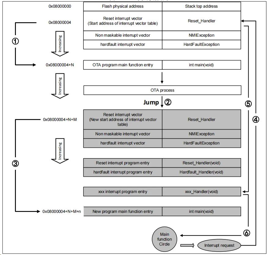
In the process shown in the above figure, after the MCU reset, it retrieves the address of the reset interrupt vector from address 0x08000004 and jumps to the reset interrupt service routine. After executing the reset interrupt service routine, it jumps to the main function of the Bootloader, as indicated by icon ①; after executing the Bootloader (the starting address of the App code’s reset interrupt vector in FLASH is 0x08000004+N+M), it jumps to the reset vector table of the App program, retrieves the address of the reset interrupt vector of the App program, and jumps to execute the reset interrupt service routine of the App program, subsequently jumping to the main function of the App program, as shown by icons ② and ③. It is also noted that at this point, the AT32’s FLASH has two interrupt vector tables at different locations.
During the execution of the main function, if the CPU receives an interrupt request, the PC pointer forcibly jumps to the address 0x08000004 interrupt vector table rather than the App program’s interrupt vector table, as indicated by icon ④; the program then jumps to the corresponding interrupt service routine based on the set interrupt vector table offset, as shown by icon ⑤; after executing the interrupt service routine, the program returns to the main function to continue execution, as shown by icon ⑥.
From the analysis of the above two processes, we understand that the OTA program must meet two requirements:
1) The App program must start at an address x offset after the Bootloader program.
2) The interrupt vector table of the App program must be appropriately moved, with an offset of x.
Quick Start Method for AT32 USART OTA
Hardware Resources
This document uses the hardware conditions of the AT-START-AT32F403A experimental board as an example. The OTA demo source code includes other models of AT32; users only need to compile the corresponding model project and program it to the AT-START experimental board for operation.
1) Indicator LEDs LED2/LED3/LED4
3) AT-START experimental board
Software Resources
1) tool_release
● IAP_Programmer.exe, a PC tool used to demonstrate the OTA upgrade process
2) source_code
● Bootloader, the Bootloader source program that runs LED2 blinking
● App_led3_toggle, App1 source program that runs LED3 blinking
● App_led4_toggle, App2 source program that runs LED4 blinking
Note: The project is based on Keil v5. If users need to use it in other compilation environments, please refer to the various compilation environments in the corresponding BSP directory AT32F403A_407_Firmware_Library_V2.x.x\project\at_start_f403a\templates for necessary modifications.
This document describes two common OTA application demos, template app and dual app, which will be introduced in the following chapters.
1) Open the Bootloader project source program, select the target corresponding to the MCU model, compile it, and download it to the experimental board
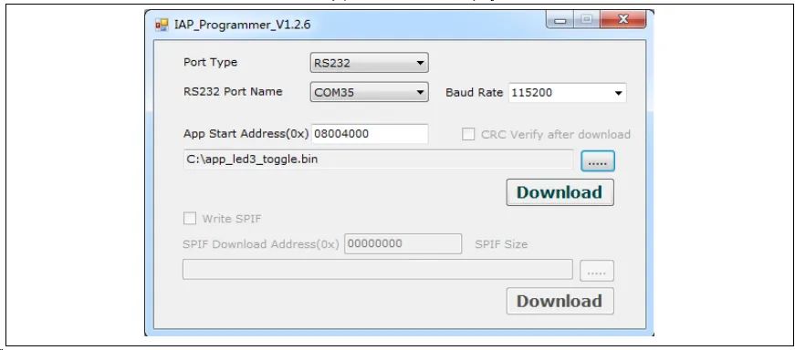
2) Open IAP_Programmer.exe
3) Select the correct serial port, APP download address, and bin document, click Download, as shown in the figure below
4) Observe LED2/3/4 blinking; LED2 blinks – Bootloader is working, LED3 blinks – App1 is working, LED4 blinks – App2 is working
Template App OTA Program Settings
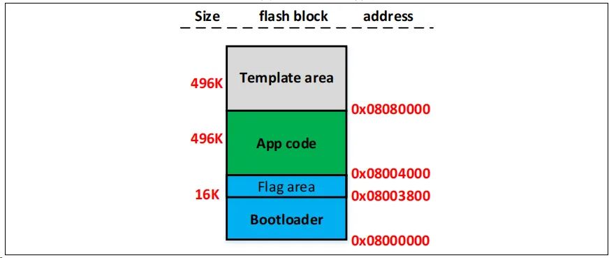
Figure 3. Flash Address Allocation
Note: The last sector of the Bootloader area is used to store a flag that prevents errors during the upgrade process (such as power outages or other abnormal situations). When users compile and modify the Bootloader, they must ensure not to overwrite the address of the flag.
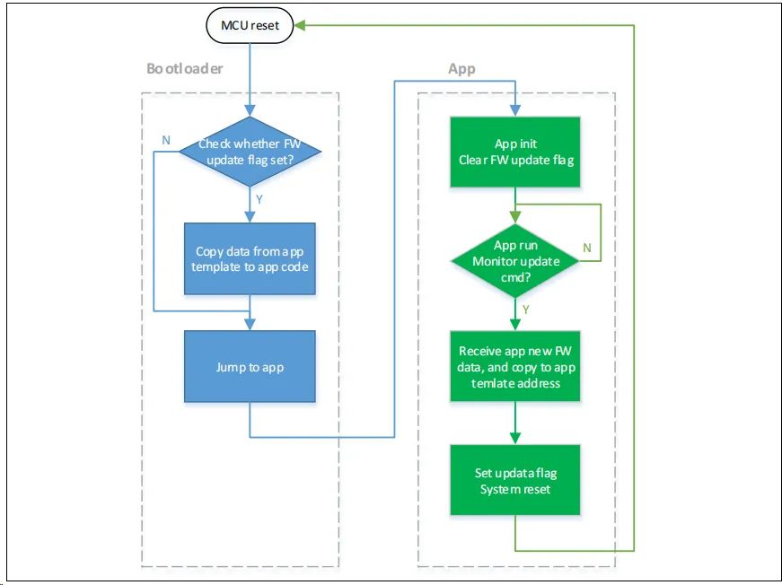
The OTA consists of three parts: Bootloader, App, and Template, with applications executed in the App. The overall program execution flowchart is as follows:
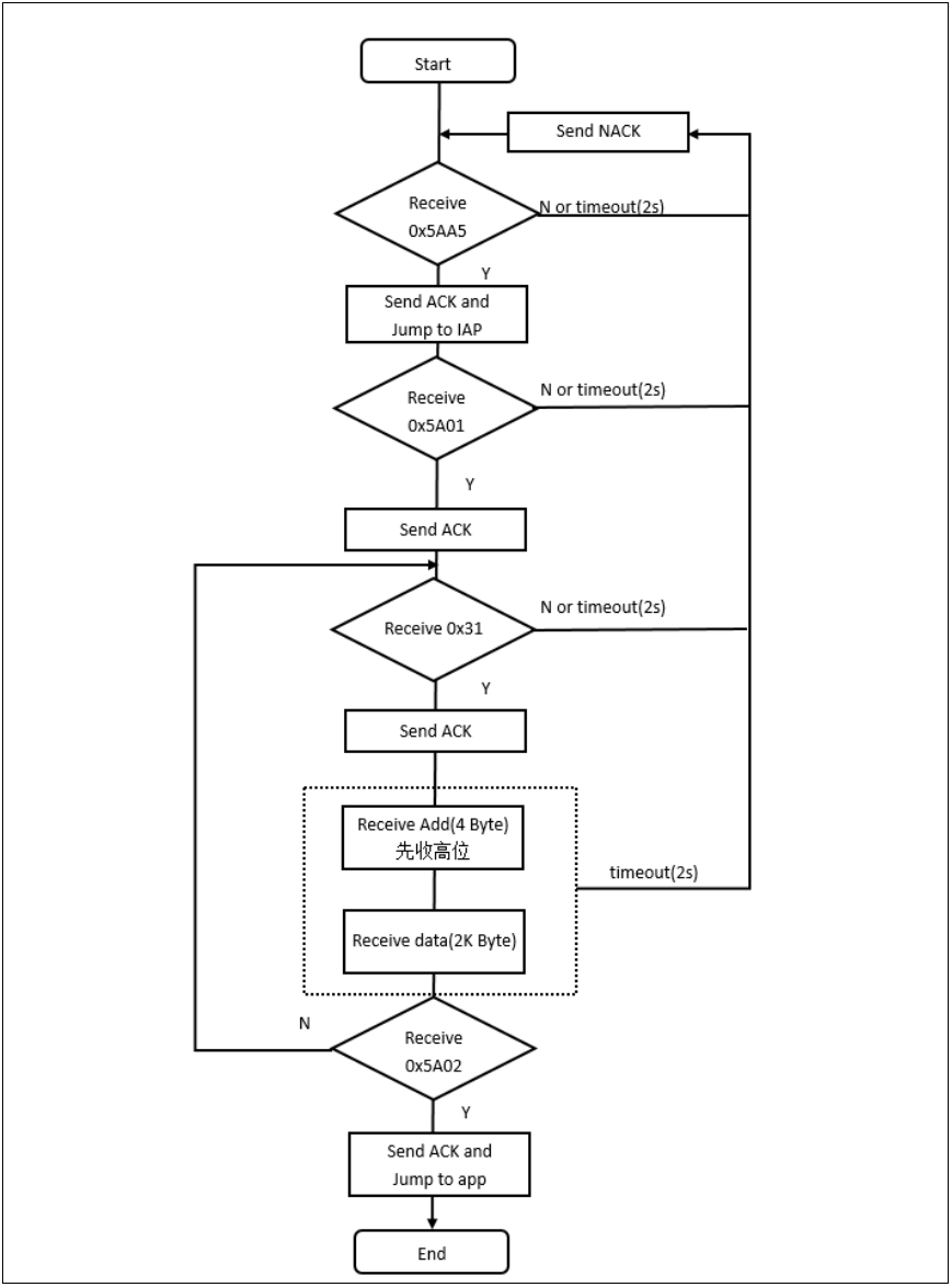
Figure 4. Program Execution Flow
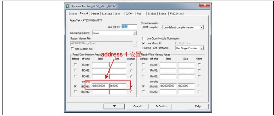
Bootloader Project Settings
Figure 5. Address 1 in Bootloader Project Settings in Keil
2) Modify the ota.h file in the Bootloader source program
Figure 6. Address 2 in Bootloader Project Settings in the Program
The OTA demo provides two App programs for testing, both starting at address 2 (0x8004000). App1 blinks LED3, and App2 blinks LED4. Using App1 as an example, the design steps are as follows:
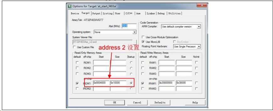
Figure 7. Address 2 in App Project Settings in Keil
2) App1 Source Program Settings
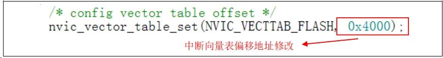
Figure 8. Vector Table Offset in App Project Settings
3) Compile to Generate bin File
Through the User tab, set up to call fromelf.exe after compilation to generate a .bin file from the .axf file for OTA updates. Through these three steps, we can obtain a .bin APP program that can be updated through the Bootloader program.
4) Enable Debug App Code Functionality
If separate debugging of the App project is needed during the design of the App code, please follow these steps.
● First download the Bootloader project
● Then debug the App project
Dual App OTA and Program Settings
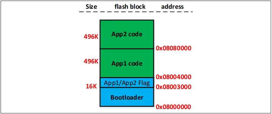
Figure 9. Flash Address Allocation
Note: The last two sectors of the Bootloader area are used to store a flag indicating whether the App is functioning normally. Users must ensure not to overwrite the address of the flag when compiling and modifying the Bootloader.
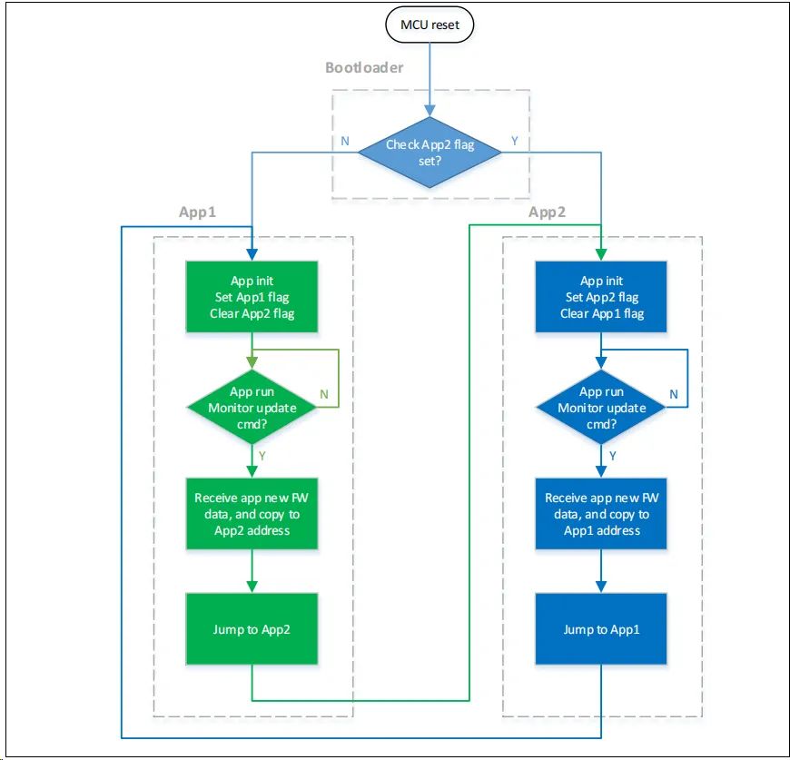
The OTA consists of three parts: Bootloader, App1, and App2, with applications executed in either App1 or App2. The overall program execution flowchart is as follows:
Figure 10. Program Execution Flow
Bootloader Project Settings
Figure 11. Address 1 in Bootloader Project Settings in Keil
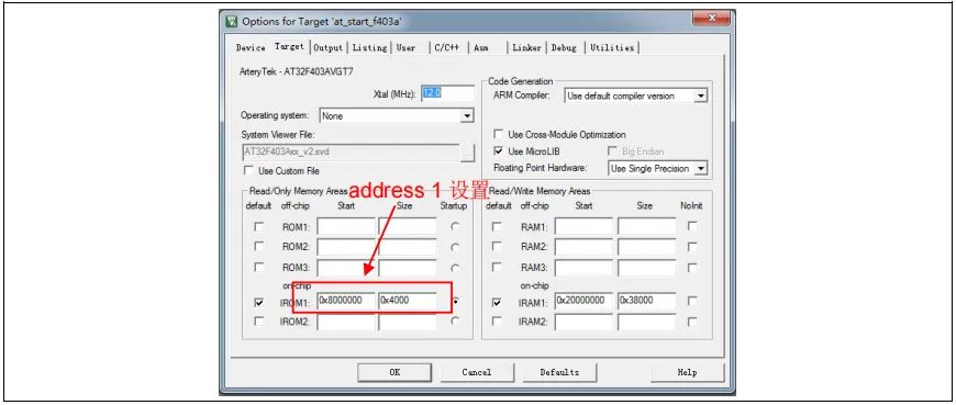
4) Modify the ota.h file in the Bootloader source program
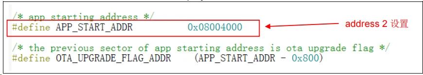
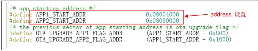
Figure 12. Address 2 in Bootloader Project Settings in the Program
The OTA demo provides two App programs for testing, app_led3_toggle starts at 0x8004000, and app_led4_toggle starts at 0x8080000. App1 blinks LED3, and App2 blinks LED4. Using App1 as an example, the design steps are as follows:
Figure 13. Address 2 in App Project Settings in Keil
6) App1 Source Program Settings
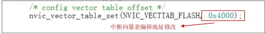
Figure 14. Vector Table Offset in App Project Settings
7) Compile to Generate bin File
Through the User tab, set up to call fromelf.exe after compilation to generate a .bin file from the .axf file for OTA updates. Through these three steps, we can obtain a .bin APP program that can be updated through the Bootloader program.
8) Enable Debug App Code Functionality
If separate debugging of the App project is needed during the design of the App code, please follow these steps.
● First download the Bootloader project
● Then debug the App project
Bootloader/App and Host Computer Serial Communication Protocol
The program communicates with the host computer to receive firmware upgrade data; the communication protocol between the host computer and the embedded system is as follows:
1) Host Computer Communication Protocol
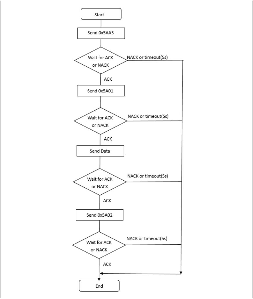
Figure 15. Host Computer Communication Protocol
2) Embedded End Communication Protocol
Figure 16. Lower Machine Communication Protocol
Data:0x31+Addr+data+checksum (1 byte)
Addr: 4 bytes, high byte first
Kbytes, download data, fill with 0xFF if less than 2K
Checksum: 1 byte, the low eight bits of the checksum for the 4 bytes of Addr + 2KBytes of data