Source | Renesas Embedded Encyclopedia
Among them, the self-diagnostic verification capability of MCUs is also a basic function, meeting the fundamental requirements of IEC 61508 (Functional safety of electrical/electronic/programmable electronic safety-related systems).

1. Development Environment
-
IDE: IAR EWARM V9.20.3 -
Development Board: EK RA6M4 -
Diagnostic Software: RTKOEF0090F60001SJ Ver1.01
2. Introduction to Self-Test Software
2.1
CPU Diagnostic Software
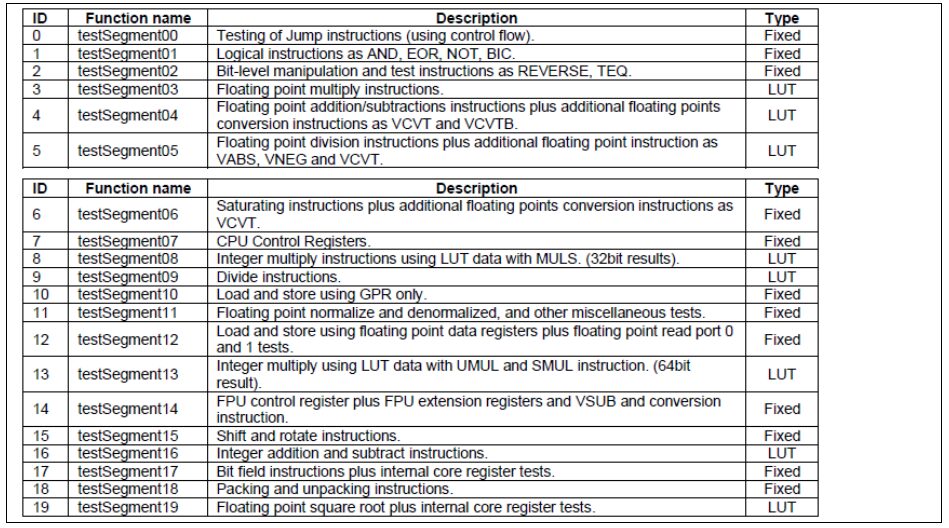
The CPU diagnostic software verifies the correct functionality of the CPU using a primarily instruction-based diagnostic method, thus detecting permanent hardware failures in the CPU core. There are 20 test items for the processor core.
2.2
CPU Diagnostic Software API
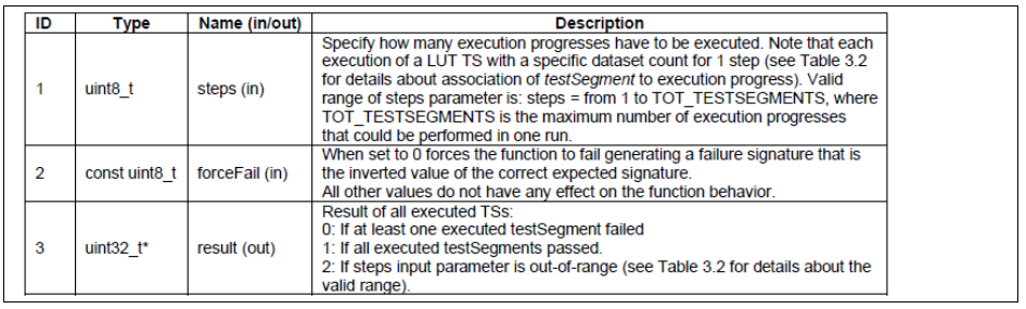
void coreTest(uint8_t steps, const uint8_t forceFail, uint32_t *result); By setting the parameter forceFail, fault injection can be performed to return an error.
2.3
RAM Diagnostic Software
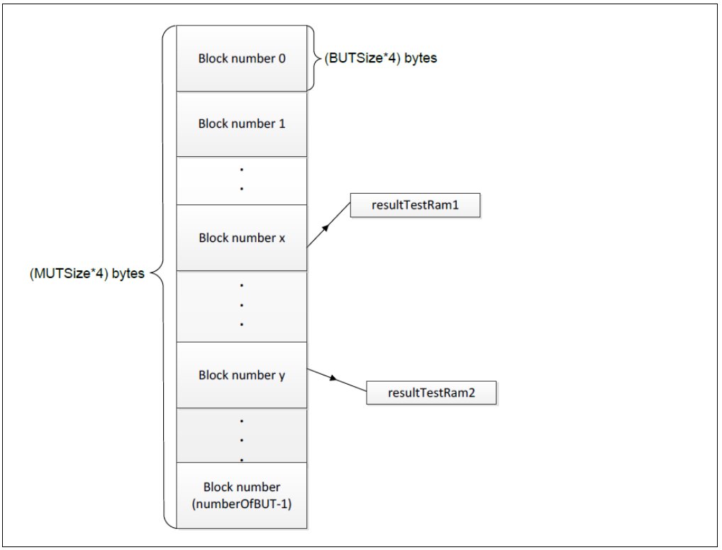
The RAM diagnostic software detects the MCU RAM memory, dividing the memory size to be tested (MUTSize) into numberOfBUT blocks, where each block size is MUTSize/numberOfBUT. The RAM diagnostic API is called to test each block of memory, returning two results: resultTestRam1 and resultTestRam2. If both are 1, the test passes; otherwise, it fails.
2.4
RAM Diagnostic Software API
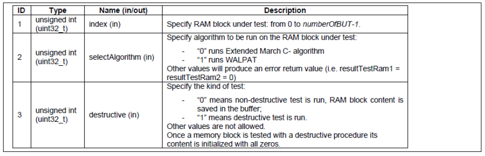
void testRAM(unsigned int index, unsigned int selectAlgorithm, unsigned int destructive); The parameter selectAlgorithm sets the RAM self-test algorithm, supporting two algorithms: Extended March C- and WALPAT. The parameter destructive sets the RAM self-test mode; 0 indicates non-destructive mode, which requires using a new buffer to save the data of the RAM area being tested as a backup, while 1 indicates destructive testing, which will clear the RAM area data and initialize it to 0.
2.5
ROM Diagnostic Software
The ROM diagnostic software detects the MCU ROM by selecting the starting and ending addresses of the ROM to confirm the range of memory blocks being tested. The ROM diagnostic API is called to perform the corresponding CRC calculation on the ROM memory block, and the returned value is compared with the reference checksum (pre-calculated by the IAR linker). If they do not match, it indicates an error.
2.6
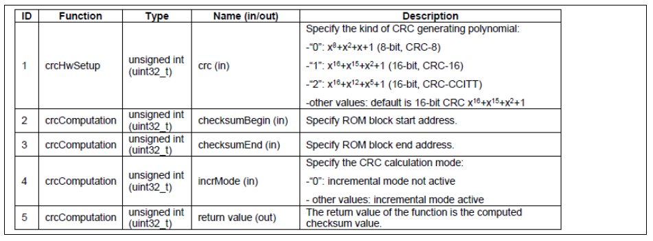
ROM Diagnostic Software API
void crcHwSetup(unsigned int crc); uint16_t crcComputation(unsigned int checksumBegin, unsigned int checksumEnd, unsigned int incrMode);
The above is an introduction to the diagnostic software; detailed information can be found in the user manual of the diagnostic software.
3. RA6 Development Board Testing
3.1 Use RASC to create an FSP project based on IAR, click Generate Project Content to generate code.


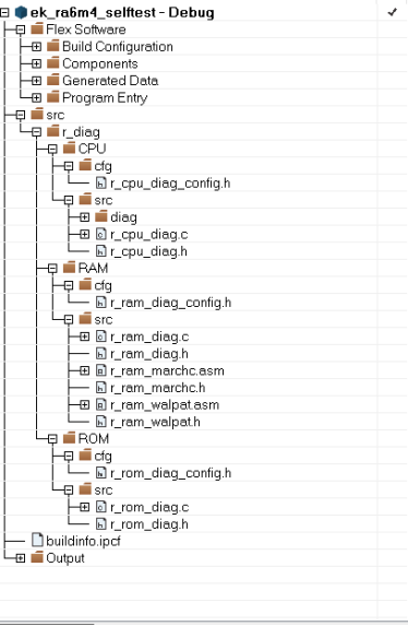
3.2 Open the newly created IAR project, copy the self-test code from the RTK0EF0090F60001SJ_Ver.1.01 code package into the src directory of the project.
3.3
Project Settings
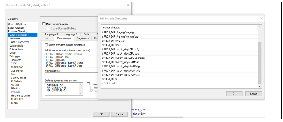
C/C++ Compiler->Preprocessor add the corresponding file path
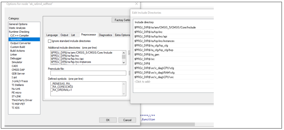
Assembler->Preprocessor add the corresponding file path
3.4
Implementation of Application Functions
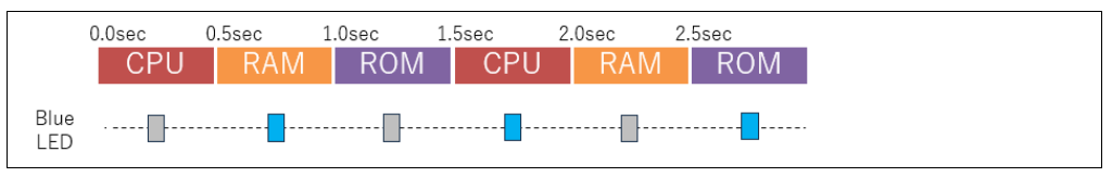
Edit the hal_entry.c file to implement a loop check of the CPU, RAM, and ROM every 0.5 seconds. At the same time, pressing the S1 button on the EK-RA6M4 inputs a fault, thus achieving CPU error detection, and the red LED flashes, referring to the ek_ra6m4_selftest sample program.
Swipe left or right to view the full content
1. Main function entry code: void hal_entry(void){    /* TODO: add your own code here */  uint32_t ver;  uint8_t cnt = 0;  ver = R_CPU_Diag_GetVersion();//  printf("CPU diag software version = %d.%02d\n",ver >>16u,ver & 0xFFFF);  ver = R_RAM_Diag_GetVersion();//  printf("RAM diag software version = %d.%02d\n",ver >>16u,ver & 0xFFFF);  ver = R_ROM_Diag_GetVersion();//  printf("ROM diag software version = %d.%02d\n",ver >>16u,ver & 0xFFFF);/* Setup Registers */  setup_diag();  /* Holds level to set for pins */  bsp_io_level_t pin_level = BSP_IO_LEVEL_LOW;  while(1)  {    int32_t result = 0;    cnt = cnt % 3;    /* Blue LED blinks */    led_change(0, pin_level);      /*  Diagnostic */    switch (cnt)    {            case 0:                            result = cpu_test_sample();                            break;            case 1:                            result = ram_test_sample();                            break;            case 2:                            result = rom_test_sample();                            break;    }        cnt++;        if (0 == result){            /* Red LED lights off */            led_change(2, BSP_IO_LEVEL_LOW);    }else{            /* Red LED lights up */            led_change(2, BSP_IO_LEVEL_HIGH);    }            /* Toggle level for next write */    if (BSP_IO_LEVEL_LOW == pin_level)    {        pin_level = BSP_IO_LEVEL_HIGH;    }    else    {        pin_level = BSP_IO_LEVEL_LOW;          }            /* Delay  (500ms) */    R_BSP_SoftwareDelay(500, BSP_DELAY_UNITS_MILLISECONDS);      } #if BSP_TZ_SECURE_BUILD    /* Enter non-secure code */    R_BSP_NonSecureEnter();#endif}
2. cpu_test_sample() function implements CPU TEST code: /************************************************************************************************************************ CPU TEST**********************************************************************************************************************/int32_t cpu_test_sample(void){    uint32_t forceFail = 1;    /* Force fail:Disable */    int32_t result;    uint32_t index; /* Check SW 'S1' */if (R_PFS->PORT[0].PIN[5].PmnPFS_b.PIDR == 0){forceFail = 0;asm("NOP");}else{asm("NOP");}     for (index = 0; index <= CPU_DIAG_MAX_INDEX; index++)    {        result = 0;        R_CPU_Diag(index, forceFail, &result);         if (result != 1) {            return -1;        }    }return 0;}
3. ram_test_sample() function implements RAM TEST code: /************************************************************************************************************************ RAM TEST**********************************************************************************************************************/#include "r_ram_diag.h" int32_t ram_test_sample(void){    uint32_t area = 0;    uint32_t index;    uint32_t algorithm = RAM_ALG_MARCHC;    uint32_t destructive;     for (index = 0; index < numberOfBUT0; index++) {        if (index == 0) {      /* Buffer block */            destructive = RAM_MEM_DT;        } else {            destructive = RAM_MEM_NDT;        }         /* Call API */        R_RAM_Diag(area, index, algorithm, destructive);         /* Check API result */        if ( (RramResult1 != 1) || (RramResult2 != 1) ) {            return -1;        }    }return 0;}
4. rom_test_sample() function implements ROM TEST code: /************************************************************************************************************************ ROM TEST**********************************************************************************************************************/ #define NUM_OB_ROM_BLOCK        (2)#define CHECKSUM_BLOCK_ADDRESS  (0x00003000) /* Area where the expected CRC checksum values of each ROM block are aggregated. */__root const uint16_t expChecksum[NUM_OB_ROM_BLOCK] @ CHECKSUM_BLOCK_ADDRESS; int32_t rom_test_sample(void){    uint32_t start;    uint32_t end;    uint32_t mode;    uint16_t calChecksum;     /* ROM Test: Block0 (4KB) */    start = 0x00001000;    end = 0x00001FFF;    mode = 0;    calChecksum = R_ROM_Diag(start, end, mode);    if (calChecksum != expChecksum[0]) {    return -1;    }     /* ROM Test: Block1 (4KB, 4time-wise split) */    /* Block1, Group1 (1KB) */    start = 0x00002000;    end = 0x000023FF;    mode = 0;    calChecksum = R_ROM_Diag(start, end, mode);     /* Block1, Group2 (1KB) */    start = 0x00002400;    end = 0x000027FF;    mode = 1;    calChecksum = R_ROM_Diag(start, end, mode);     /* Block1, Group3 (1KB) */    start = 0x00002800;    end = 0x00002BFF;    calChecksum = R_ROM_Diag(start, end, mode);     /* Block1, Group4 (1KB) */    start = 0x00002C00;    end = 0x00002FFF;    calChecksum = R_ROM_Diag(start, end, mode);    if (calChecksum != expChecksum[1]) {return -1;    }return 0;}
The highlights of the annual MCU/MPU industrial technology seminar are here!
Renesas MCU’s rise in recent years
Learning path and technical points of Modbus
Recommended Reading:
Renesas RA8 Series Tutorial | Introduction to Renesas RA8 Series Microcontrollers
Renesas RA8 Series Tutorial | Setting up the Renesas RA8 Development Environment and Lighting Up an LED
Renesas RA8 Series Tutorial | Developing the RA8 Microcontroller Based on Keil
Renesas RA8 Series Tutorial | Learning What Documents and Manuals are Commonly Used for RA8
Renesas RA8 Series Tutorial | Configuring IO Interrupts for the RA8 Microcontroller
Renesas RA8 Series Tutorial | Methods to Run RTOS on RA8 Based on e2s
Renesas RA8 Series Tutorial | Configuring Serial Output for RA8 Based on e2s
Renesas RA8 Series Tutorial | Description of SysTick Usage for RA8 Microcontroller
Renesas RA8 Series Tutorial | Methods to Implement PWM Output for RA8
······