Write summaries, discuss careers, and win DJI drones, Redmi tablets, Huawei headphones, and JD gift cards!Participate in the “End of Year Summary and Career Discussion” event, share your past experiences in the electronics industry, or summarize your 2023.
Project Development Background
The construction of the rail inspection robot is achieved through an intelligent rail-based inspection robot that utilizes 5G communication technology, equipped with data collectors and real-time intelligent analysis software, to detect gas and combustible gases, and eliminate safety hazards through alarms. It creates a standardized, modernized, and intelligent security inspection solution. It improves inspection efficiency and also reduces costs and operational expenses.
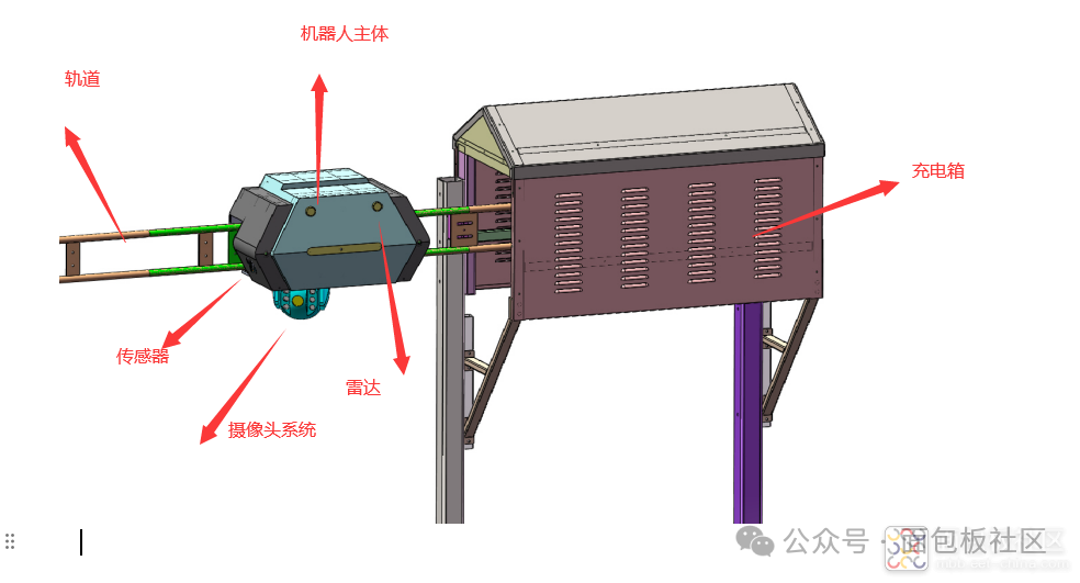
The suspended rail inspection robot mainly consists of the robot body, charging box, rail section, and camera sensor system. The entire system can be used for inspections in enterprise parks, campus areas, chemical factories, substations, high-speed railways, mines, etc. By using overhead rails, it avoids human interference, ensuring high safety. Various sensor system modules can be replaced to adapt to different inspection scenarios. The communication system is based on 5G/4G, Lora modules, bridge modules, etc., enabling real-time control without an operator’s network, whether online or offline.
Embedded System Hardware Design
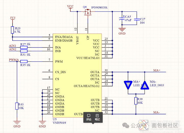
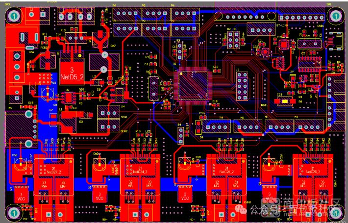
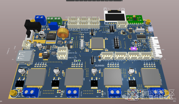
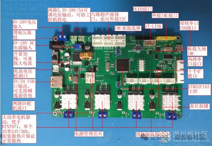
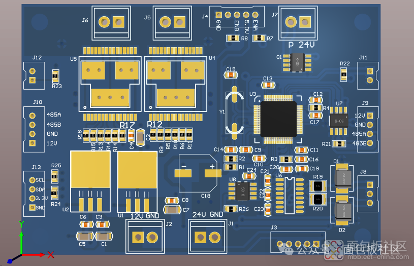
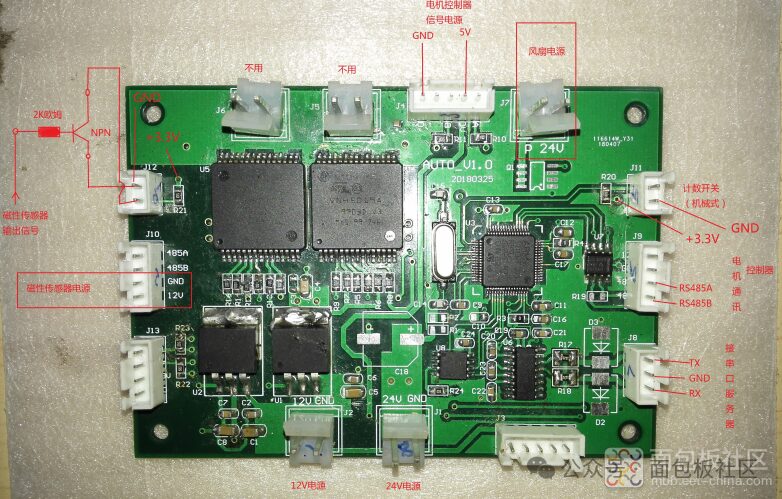
The main control circuit board uses the STM32 microcontroller. The motor driver chip used in the project is BTN7971A, and VHN5019A is a full-bridge motor driver, AEC-Q100 certified. The MultiPowerSO-30 package is designed for harsh automotive environments. Due to the use of exposed chip pads, it can provide better thermal performance. It is suitable for various automotive-grade motor applications. This device contains a dual high-side driver and two low-side switches. The high-side driver switches are designed using STMicroelectronics’ well-known and proven proprietary VIPower® M0 technology, which allows for effective integration of a true low-power MOSFET on the same chip, along with intelligent signal/protection circuits. The input signals INA and INB of the VNH5019ATR-E three-chip assembly can be directly connected to the microcontroller to select motor direction and braking conditions.
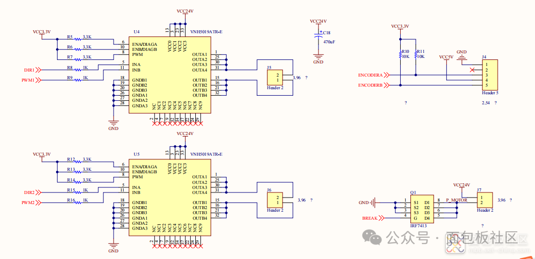
 Another IC from ST is the VNH5019 full-bridge motor driver IC, which is cost-effective. A single chip can drive one DC motor. Four chips can drive four motors. The driver does not need to be connected via a dedicated bus; it only requires two digital pins to control direction, one PWM pin to control speed, and one analog pin (optional) to read the current flowing through the motor.
Software Design:The main controller uses the STM32F103 with a Cortex-M3 core. The controller has a total of 8 timers, among which TIM1_CH1 and TIM8_CH1 are advanced control timer pins. TIM1_CH1 is used for motor encoder counting. TLM8_CH1 is used for the reference time of servo control. General timer pins TIM2 CH1, TIM3 CH1, TIM4_CH1, and TIM5_CH1 are used to generate PWM for the upper and lower bridge walls of the motor and servo driver circuits. The PA0 and PB0 pins that trigger the EXIT0 interrupt are used for motor overcurrent interrupt protection.
Another IC from ST is the VNH5019 full-bridge motor driver IC, which is cost-effective. A single chip can drive one DC motor. Four chips can drive four motors. The driver does not need to be connected via a dedicated bus; it only requires two digital pins to control direction, one PWM pin to control speed, and one analog pin (optional) to read the current flowing through the motor.
Software Design:The main controller uses the STM32F103 with a Cortex-M3 core. The controller has a total of 8 timers, among which TIM1_CH1 and TIM8_CH1 are advanced control timer pins. TIM1_CH1 is used for motor encoder counting. TLM8_CH1 is used for the reference time of servo control. General timer pins TIM2 CH1, TIM3 CH1, TIM4_CH1, and TIM5_CH1 are used to generate PWM for the upper and lower bridge walls of the motor and servo driver circuits. The PA0 and PB0 pins that trigger the EXIT0 interrupt are used for motor overcurrent interrupt protection.
#include "pwm.h"
void TIM1_Int_Init(u16 arr, u16 psc){
    TIM_TimeBaseInitTypeDef  TIM_TimeBaseStructure;
    TIM_OCInitTypeDef  TIM_OCInitStructure;
    GPIO_InitTypeDef GPIO_InitStructure;
    RCC_APB2PeriphClockCmd(RCC_APB2Periph_TIM1, ENABLE);
    RCC_APB2PeriphClockCmd(RCC_APB2Periph_GPIOA, ENABLE);
    GPIO_InitStructure.GPIO_Pin = GPIO_Pin_8 | GPIO_Pin_9 ;
    GPIO_InitStructure.GPIO_Mode = GPIO_Mode_AF_PP;
    GPIO_InitStructure.GPIO_Speed = GPIO_Speed_50MHz;
    GPIO_Init(GPIOA, &GPIO_InitStructure);
    TIM_TimeBaseStructure.TIM_Period = arr;
    TIM_TimeBaseStructure.TIM_Prescaler = psc;
    TIM_TimeBaseStructure.TIM_ClockDivision = TIM_CKD_DIV1;
    TIM_TimeBaseStructure.TIM_CounterMode = TIM_CounterMode_Up;
    TIM_TimeBaseInit(TIM1, &TIM_TimeBaseStructure);
    TIM_OCInitStructure.TIM_OCMode = TIM_OCMode_PWM1;
    TIM_OCInitStructure.TIM_OutputState = TIM_OutputState_Enable;
    TIM_OCInitStructure.TIM_Pulse = 0;
    TIM_OCInitStructure.TIM_OCPolarity = TIM_OCPolarity_High;
    TIM_OC1Init(TIM1, &TIM_OCInitStructure);
    TIM_OC1PreloadConfig(TIM1, TIM_OCPreload_Enable);
    TIM_OCInitStructure.TIM_OutputState = TIM_OutputState_Enable;
    TIM_OCInitStructure.TIM_Pulse = 0;
    TIM_OC2Init(TIM1, &TIM_OCInitStructure);
    TIM_OC2PreloadConfig(TIM1, TIM_OCPreload_Enable);
    TIM_ARRPreloadConfig(TIM1, ENABLE);
    TIM_CtrlPWMOutputs(TIM1, ENABLE);
    TIM_Cmd(TIM1, ENABLE);
}
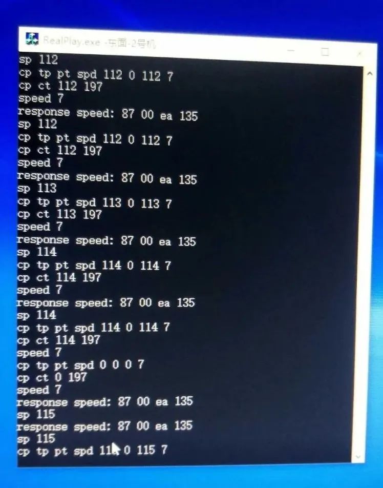
Based on actual operational needs, the PC upper computer gives the robot inspection speed and inspection position through Ethernet to serial conversion. The motor speed is compared with the set speed value and the value collected by the incremental encoder, achieving closed-loop control through a speed PID algorithm. The robot’s position is mainly fed back by the absolute encoder to adjust the servo rotation speed based on motion time requirements. The functions that the robot motor control system software needs to achieve are as follows:
◆ The upper computer specifies speed, inspection position, and inspection time settings, and sets position points; ◆ Requires the motor speed to be continuously adjustable with good static and dynamic performance, with speed measurement adjusted by a PI algorithm; ◆ Requires the robot to quickly reach the specified angle, with position feedback for adjusting the motor’s set speed; ◆ Has certain fault protection functions. When the motor stalls, the current is too high, or the servo touches the limit switch, it is required to stop the driving module from working.
To achieve the above functions, the application program design can be divided into the following tasks: 1) Start Task. Initializes the system, creates the initial motor state, then self-deletes, and the startup task enters sleep mode. 2) Motor and Servo Protection Task. Responds to external interrupts when overcurrent or limit switch actions occur, enters interrupt state, sends task signals, and the task program detects the validity of the signal and responds to that task, stopping output. The task priority is set to level 0. 3) Upper Computer Given Task. Used for upper computer control of motors and servos, with task priority set to level 1. When data is input into the upper computer data register, an interrupt is generated, sending the received bytes into the buffer and releasing the upper computer given task’s semaphore; when the task detects the semaphore is valid, it begins execution, parsing the corresponding byte information into corresponding motor speed and servo angle position information and assigning values to the respective variables. 4) Motor Speed Control Task. Used for closed-loop speed control of the motor, with task priority set to level 2. 5) Servo Control Task. Used to control the servo to reach the specified position within a set time, with task priority set to level 3.
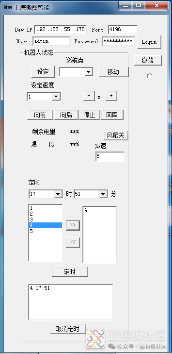
A PC-side application developed based on C++ QT, displays the robot’s position and monitors video in real-time through Ethernet, controls the battery level; displays the robot’s internal temperature; controls the fan switch; the robot operates in both manual and automatic cruising modes:
1) Manual mode control is relatively simple; first set the speed, usually designed in three gears, then press forward, backward, stop, or return to the warehouse, and the robot will perform corresponding actions.
2) In automatic mode, first run manually once, then based on Realplay data or visual reference objects, set the cruising points. The maximum east is 210, and the maximum north is 172. Then set the inspection time period, and the robot will automatically cruise.
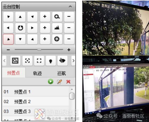
PTZ Control Introduction:
Control the PTZ rotation in 8 directions using the arrow keys, and control the rotation speed of the PTZ using the slider. Click to start automatic scanning of the PTZ, and click again to stop the automatic scanning. The right function button allows for adjustments in focal length, aperture, and zoom. The PTZ control interface provides many shortcut keys for ball machine functions, including 3D positioning, auxiliary focus, light wiper control, manual tracking, one-click surveillance, one-click cruising, ball machine menu invocation, manual de-icing, etc. Click to view the remaining shortcut keys.
Author: abner_ma, Source: Breadboard CommunityLink: https://mbb.eet-china.com/forum/topic/139259_1_1.html Disclaimer: This article is an original work by a community user, and the content does not represent the views and positions of this account.
Write Summaries, Discuss Careers!

Award Settings:First Prize (1): DJI Mini 3
Second Prize (2): ITECH adjustable DC regulated power supply/Redmi tablet, choose one
Third Prize (3): Huawei FreeBuds 4E headphones (¥458)
Participation Prize (20): JD gift card worth 50 yuan
The evaluation will be based on the quality of the article, platform data, etc., and senior engineers will also be invited to provide feedback.
 Click to read the original text to participate in the event!