
RS-485 (RS232 to RS485) bus interface, as an electrical specification for multipoint and differential data transmission, has become one of the most widely used standard communication interfaces in the industry. The RS-485 standard specifies only the electrical characteristics of the interface and does not involve connectors, cables, or protocols, allowing users to establish their own higher-level communication protocols based on this.
The RS-485 bus communication mode is widely used in instruments, intelligent sensor distributed control, building control, monitoring, and alarm systems due to its simple structure, low cost, appropriate communication distance, and data transmission rate. However, RS-485 buses have disadvantages such as weak adaptive and self-protective functions; if some details are not properly handled, communication failures or even system crashes may occur, making it crucial to enhance the operational reliability of the RS-485 bus.
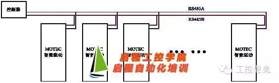
Network topology generally adopts a bus-type structure with terminal matching and does not support ring or star networks. Bus nodes are connected in a daisy chain or bus topology, meaning each node is connected to the main cable via a short wire. This interface bus is typically designed for half-duplex transmission, meaning it uses only one pair of signal wires, and driving data and receiving data can only appear on the signal line at different times.
Below is a topology diagram controlled by the MOTEC intelligent driver through the RS485 network.
As for RS485 cables (RS485 to RS232), ordinary twisted pairs can be used in general situations, while shielded coaxial cables can be used in more demanding environments.
Optical Isolation Circuit
In some industrial control fields, due to the complexity of the field conditions, there is a high common-mode voltage between the nodes. Although the RS-485 interface uses differential transmission, which has a certain ability to resist common-mode interference, when the common-mode voltage exceeds the maximum receiving voltage of the RS-485 receiver (greater than 12V or less than -7V), the receiver can no longer operate normally, and in severe cases, it may even burn out the chip and equipment.
The solution to such problems is to isolate the system power and the RS-485 transceiver power through a DC-DC converter; and to isolate the signal using optocouplers, completely eliminating the impact of common-mode voltage.
Signal Reflection (Matching with Terminating Resistors)
During communication, signal reflection can occur due to two reasons: impedance discontinuity and impedance mismatch. Impedance discontinuity occurs when a signal suddenly encounters a very low or zero impedance at the end of the transmission line, causing reflection. This principle of signal reflection is similar to light reflecting when it transitions from one medium to another. To eliminate this reflection, a terminating resistor matching the characteristic impedance of the cable must be bridged at the end of the cable to maintain impedance continuity. Since signal transmission on the cable is bidirectional, a matching terminating resistor can also be bridged at the other end of the communication cable.
Bus Isolation (Connecting Low Resistance and Bridging Diodes between Interface Lines and Bus)
The RS-485 bus is a parallel two-wire interface; once one chip fails, it may cause the bus to be “pulled down.” Therefore, a 4-10 Ω PTC resistor should be connected in series between the two-wire ports VA and VB and the bus, while bridging a 5V TVS diode to ground to eliminate line surge interference. Additionally, chips should be selected reasonably. For external devices, it is recommended to use lightning-protection chips to prevent strong electromagnetic shocks.
Grounding Issues
(1) Common Mode Interference Issues
The RS-485 interface uses differential transmission, which does not require a reference point to detect signals; the system only needs to detect the potential difference between the two wires. However, it is important to note that the transceiver can only operate normally when the common-mode voltage does not exceed a certain range (between -7V and 12V). When the common-mode voltage exceeds this range, it will affect the reliability of communication and may damage the interface.
(2) Electromagnetic Interference (EMI) Issues
The common-mode part of the output signal from the driver requires a return path; if there is no low-resistance return path (signal ground), it will return to the source end in the form of radiation, causing the entire bus to act like a large antenna radiating electromagnetic waves. Therefore, despite differential transmission, a low-resistance signal ground is still required for RS-485 networks.
The MOTEC intelligent driver fully supports various application layer communication protocols based on RS485, such as MODBUS RTU, DMX512, and various MOTEC custom protocols, supporting multiple networking. MOTEC is vigorously promoting the prevalence and intelligence of network control methods in the automation industry.
About Us: Qicheng Automation Training, China’s leading provider of industrial robot training services.
Contact Number: 13809869603
Training Programs:Robotics + PLC System Integration + Motion Control + Robotics + Machine Vision
Special Services: 3000 square meter training center + job placement + industry-leading course system

+ Teacher WeChat for course details
Click to like before you leave