【Introduction】Starting from version V15 of TIA Portal, the Modbus (RTU) instruction set has been updated to version V4.0 and above. The S7-1200 firmware must be at least version V4.2. This article mainly discusses the new features of Modbus RTU version 4 and above.
 S7-1200 Motion Control Example Download
 S7-1500 Analog Module Wiring Diagram
 PLC Manual and Automatic Programming Methods
 Useful Siemens Programming Tips
(1) Overview
Taking version V16 as an example, as shown in Figure 1, the Modbus (RTU) instruction set is version V4.4. The following important features have been updated in this version of the Modbus RTU instructions.
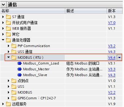
Figure 1 Modbus RTU V4 Instruction Set1. Changes to Modbus_Master Instructions:
- The DB of the DATA_PTR interface can support “optimized block access”
2. Changes to Modbus_Slave Instructions:
- The DB of the MB_HOLD_REG interface can support “optimized block access”
- Read access restrictions can be selected for the input/output process image area
- Custom access to data areas in the DB can be defined instead of the default IQ area and MB_HOLD_REG)
(2) Support for Optimized Blocks
The DATA_PTR parameter points to the DB or M address to be written to or read from. If using a data block, a global data block must be created to provide a data storage location for reading and writing Modbus slaves.1. Since instruction version V4.0:This parameter can point to an optimized DB data block, where single elements or arrays of the following data types are allowed: Bool, Byte, Char, Word, Int, DWord, DInt, Real, USInt, UInt, UDInt, SInt, or WChar. MB_HOLD_REG points to the Modbus RTU holding register, which can be in the M storage area or DB data block.2. Since instruction version V4.0:This parameter can point to an optimized DB data block, where single elements or arrays of the following data types are allowed: Bool, Byte, Char, Word, Int, DWord, DInt, Real, USInt, UInt, UDInt, SInt, or WChar.3. Example:Using V16 TIA Portal software, configure the CM1241 RS422/485 module as a Modbus RTU master on the 1215CPU, and configure the CM1241 RS422/485 module as a Modbus RTU slave on the 1214CPU.(1) Write the Modbus master program in OB1 for the 1215CPU, create the optimized DB data block DB3-Master, and fill the DATA_PTR with the area of this optimized DB block:
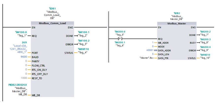
Figure 2 Modbus Programming for 1215CPU Master
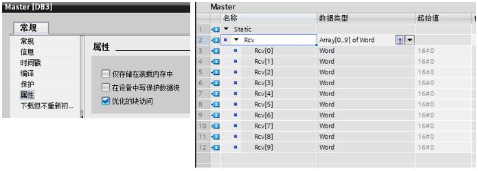
Figure 3 Optimized Data Block DB3-Master(2) Write the Modbus slave program in OB1 for the 1214CPU, create the optimized DB data block DB8, and fill the MB_HOLD_REG with the area of this optimized DB block:
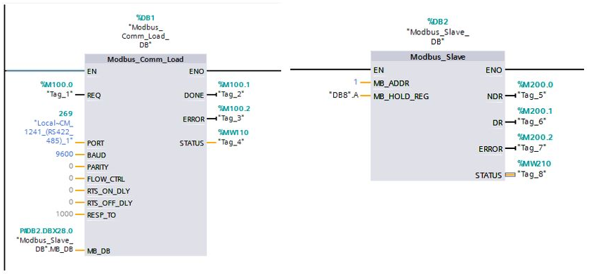
Figure 4 Modbus Programming for 1214CPU Slave
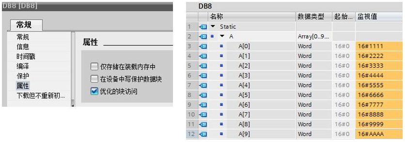
Figure 5 Optimized Data Block DB8(3) The REQ pin of the master triggers, and the master reads the holding register 40001 from the slave, with a length of 5 words. The reading result is shown in the figure:
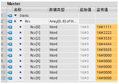
Figure 6 Data Read by Master
(3) Usage of Modbus Slave Instructions
1. The background DB data content of Modbus_Slave V4 is shown in Figure 7:
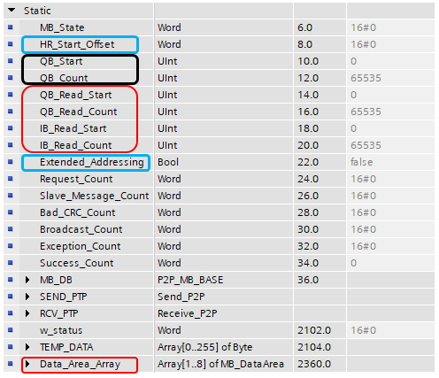
Figure 7 Modbus_Slave V4 Background Data Block2. User programs can modify the variables circled in Figure 7:(1) The red variables are added in the Modbus_Slave V4 instruction set, requiring TIA Portal version V15 or above, and CPU version V4.2 or above.
- QB_Read_Start
- QB_Read_Count
- IB_Read_Start
- IB_Read_Count
- Data_Area_Array
(2) The black variables are added in the Modbus_Slave V3 instruction set, requiring TIA Portal version V14SP1 or above, and CPU version V4.1.1 or above.
- QB_Start
- QB_Count
(3) The blue variables are from the Modbus_Slave V2 instruction set (i.e., the initial version), requiring TIA Portal version V13SP1 or above, and CPU version V4.1.1 or above.
- HR_Start_Offset
- Extended_Addressing
(4) Process Image Read/Write Access Restrictions
1. Definition of writable areas in the process image:QB_Start: The starting address of the output bytes that the CPU can write toQB_Count: The number of output bytes that the CPU can write to. If QB_Count = 0, then all output bytes of the CPU cannot be written.The default is QB_Start = 0, QB_Count = 65535, meaning all output byte areas can be read and written.Example: To allow only QB10 to QB17 to be writable, set QB_Start = 10 and QB_Count = 8.2. Definition of readable areas in the process image:QB_Read_Start: The starting address of the output bytes that the CPU can readQB_Read_Count: The number of output bytes that the CPU can read. If QB_Read_Count = 0, then all output bytes of the CPU cannot be read.The default is QB_Read_Start = 0, QB_Read_Count = 65535, meaning all output byte areas can be read.Example: To allow only QB10 to QB17 to be readable, set QB_Read_Start = 10 and QB_Read_Count = 8.IB_Read_Start: The starting address of the input bytes that the CPU can readIB_Read_Count: The number of input bytes that the CPU can read. If IB_Read_Count = 0, then all input bytes of the CPU cannot be read.The default is IB_Read_Start = 0, IB_Read_Count = 65535, meaning all input byte areas can be read.Example: To allow only IB10 to IB17 to be readable, set IB_Read_Start = 10 and IB_Read_Count = 8.
(5) Accessing Data Areas in DB Instead of Directly Accessing Modbus Addresses
Starting from Modbus_Slave instruction version V4.0 and S7-1200 CPU firmware (FW) version V4.2, users can access data areas in data blocks without directly accessing the process image and holding registers. To do this, the “Only store in load memory” and “Optimize block access” checkboxes must be unchecked in the global DB property page.1. If a MODBUS request arrives and the corresponding MODBUS data type data area for the function code is not defined, the request will be processed according to the previous instruction version, i.e., directly accessing the process image and holding registers.2. If a MODBUS request arrives and the data area for the defined function code is available, the Modbus_Slave instruction will perform read/write operations on this data area. Whether it is a read or write operation depends on the job type.3. A single MODBUS request can only perform read/write operations on one data area. If you want to read holding registers that cover multiple data areas, multiple MODBUS requests are needed.4. The definition rules for data areas are as follows:
- Up to 8 data areas can be defined, located in Data_Area_Array[1..8].
- The definition of data area array elements must be continuous; if a middle array element definition is invalid, subsequent areas will not be effective.
- If a holding register is defined in the data area, the MB_HOLD_REG mapping becomes invalid; if a process image output is defined in the data area, the corresponding Q area mapping becomes invalid; if a process image input is defined in the data area, the corresponding I area mapping becomes invalid; if an input register is defined in the data area, the corresponding AI area mapping becomes invalid. In other words, if no area is defined in the data area, the original mapping remains.
- A single MODBUS request can only perform read/write operations on exactly one data area.
- Each field element Data_Area_Array[x] (where 1 <= x <= 8) is of type MB_DataArea UDT, with the structure as shown in Table 1:
| Parameter | Data Type | Meaning |
|---|---|---|
| data_type | UInt |
Identifier for the MODBUS data type mapped to this data area:• 0: Identifier for empty field elements or unused data areas. At this time, the values of db, start, and length are invalid. • 1: Process image output (used with function codes 1, 5, and 15) • 2: Process image input (used with function code 2) • 3: Holding register (used with function codes 3, 6, and 16) • 4: Input register (used with function code 4) |
| db | UInt |
The number of the mapped data area; this DB must be a non-optimized DB |
| start | UInt |
The first MODBUS address mapped to the data block, starting from 0 |
| length | UInt |
Number of Bools (for data_type 1 or 2), number of Words (data_type 3 or 4) |
Table 1 Elements of Data_Area_Array and Their Meanings4. Example:In this example, using V16 TIA Portal software, configure the CM1241 RS422/485 module as a Modbus RTU master on the 1215CPU, and configure the CM1241 RS422/485 module as a Modbus RTU slave on the 1214CPU. The master accesses the data area in the data block (DB) of the slave:(1) Master configuration: In OB1, drag in the Modbus_Comm_Load instruction and the Modbus_Master instruction, with MODE=0, DATA_ADDR=40006, DATA_LEN=5, as shown in Figure 8:
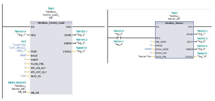
Figure 8 Master Calls Master Instruction(2) Slave configuration: In OB1, drag in the Modbus_Comm_Load instruction and the Modbus_Slave instruction, referring to the configuration in Figure 4,the Data_Area_Array in the background DB of the slave is configured as shown in Figure 9:
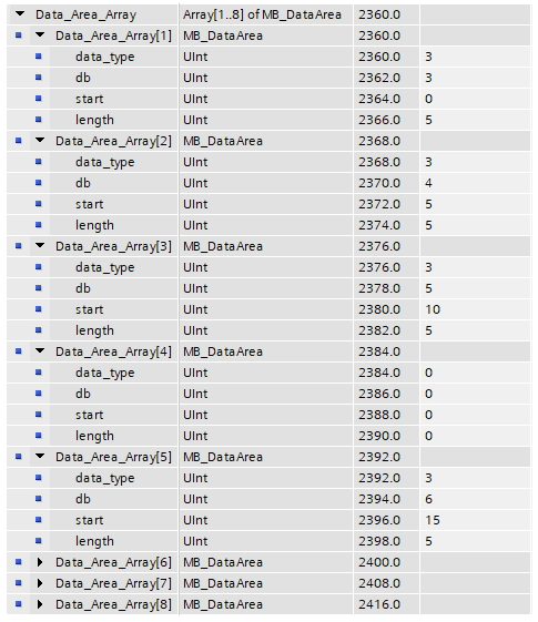
Figure 9 Data_Area_Array in 1214CPU Modbus_Slave Background DBData_Area_Array[1]:data_type = 3, db = 3, start = 0, length = 5, which corresponds to DB3.DBW0-DB3.DBW8 for addresses 40001-40005.Data_Area_Array[2]:data_type = 3, db = 4, start = 5, length = 5, which corresponds to DB4.DBW0-DB4.DBW8 for addresses 40006-40010.Data_Area_Array[3]:data_type = 3, db = 5, start = 10, length = 5, which corresponds to DB5.DBW0-DB5.DBW8 for addresses 40011-40015.Data_Area_Array[4]:data_type = 0, db = 0, start = 0, length = 0.Data_Area_Array[5]:data_type = 3, db = 6, start = 15, length = 5, which corresponds to DB6.DBW0-DB6.DBW8 for addresses 40016-40020. Since the Data_Area_Array[4] parameter is empty, the Data_Area_Array[5] parameter becomes invalid.(3) Create 4 non-optimized DB blocks in the 1214CPU, DB3/DB4/DB5/DB6, as shown in Figure 11:
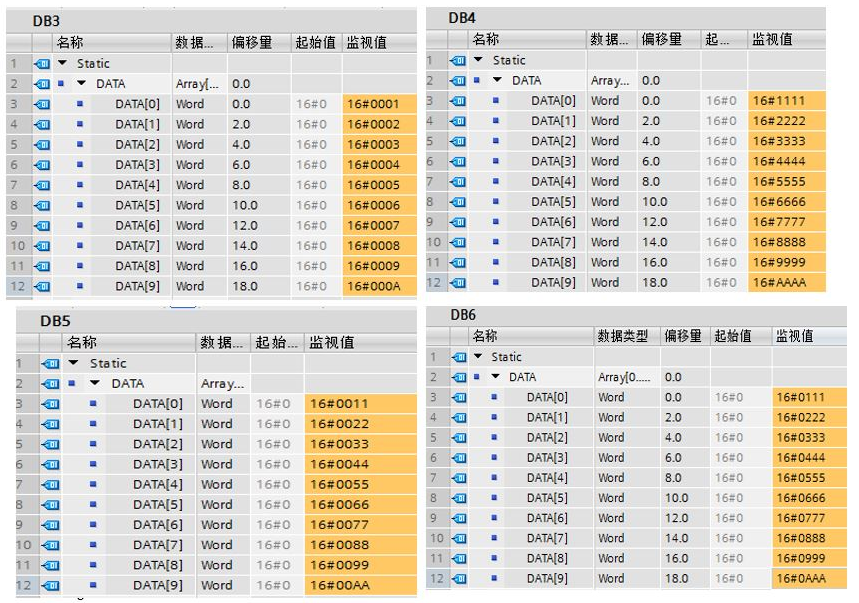
Figure 11 1214CPU Creating Data Blocks(4) The Master block of the 1215CPU reads addresses 40006-40010, corresponding to the contents of DB4.DBW0-DB4.DBW8 in the 1214CPU, and the Master block reads the content as shown in Figure 12:
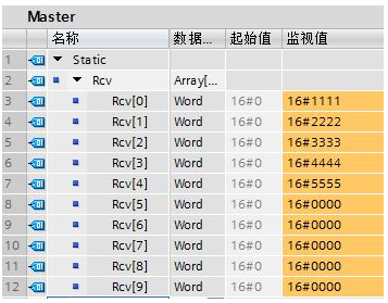
Figure 12 Data Read by Master CPU(5) If the Master reads the Modbus address 40016 from the slave with a data length of 5, as shown in Figure 13:
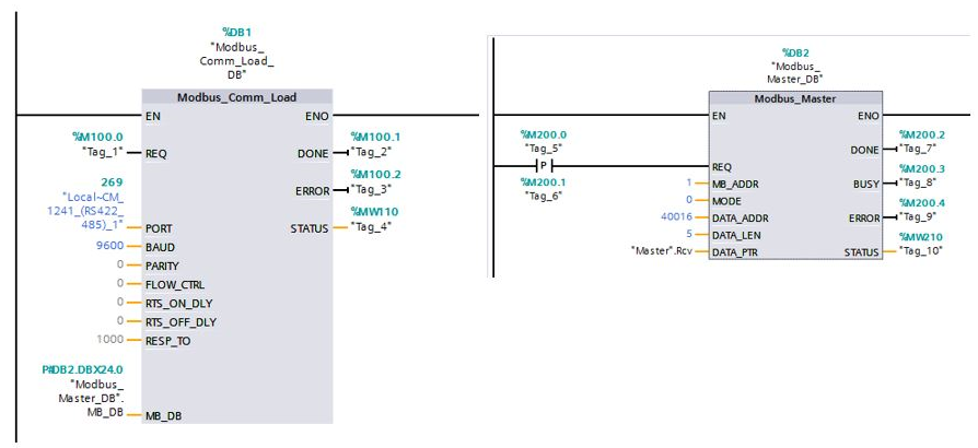
Figure 13 Master Calls Master Instruction(6) Since the slave 1214CPU does not have data areas corresponding to addresses 40016-40020, an error occurs after executing the Master instruction, as shown in Figure 14,16#8383: Invalid data address in the request frame.
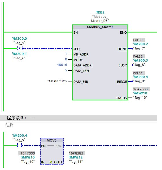
Figure 14 Error Executing Master Instruction
(6) HR_Start_Offset
1. HR_Start_Offset is used to specify the starting address of the Modbus holding register, stored in the Modbus_Slave background data block, with a default of 0.2. The Modbus holding register address starts from 40001 or 400001. These addresses correspond to the starting address of the holding register in the PLC memory. By configuring the “HR_Start_Offset” variable, the starting address of the Modbus holding register can be defined as a value other than 40001 or 400001.(1) For example, if the holding register is configured to start at MW100 and has a length of 100 words (i.e., MB_HOLD_REG set to P#M100.0 WORD 100). An offset of 20 can specify the starting address of the holding register as 40021 instead of 40001. Any address below 40021 and above 400119 will result in addressing errors.
| HR_Start_Offset | Address | Minimum Value | Maximum Value |
|---|---|---|---|
| 0 | Modbus Address | 40001 | 40099 |
| S7-1200 Address | MW100 | MW298 | |
| 20 | Modbus Address | 40021 | 40119 |
| S7-1200 Address | MW100 | MW298 |
(2) For example, after placing Modbus_Slave in the LAD program segment, you can switch back to the previous program segment and assign the HR_Start_Offset value. This value must be assigned before executing Modbus_Slave, as shown in Figure 6:
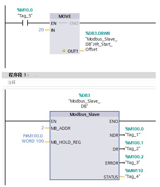
Figure 15 Slave ProgrammingNote: It is not recommended to modify the HR_Start_Offset when using Data_Area_Array to modify the holding register area.
(7) Extended_Addressing
Modbus slave addressing can be configured as single-byte (standard Modbus method) or double-byte. Extended addressing is used for addressing more than 247 addresses within a single network. When extended addressing is selected, up to 65535 addresses can be addressed.1. Extended_Addressing is FALSE (default setting): 1-byte address, address range 0 to 247.2. Extended_Addressing is TRUE: 2-byte address, address range 0 to 65535.
What Everyone is Watching
 [Video] How German Engineers Make PLC Cabinets?
 [Video] How German WITRON Electrical Cabinets are Produced?
 [Video] What is the Office Environment of German Engineers Like?
 [Video] Why is PROFINET Better than PROFIBUS?