Are you still using those outdated manual scoreboards? It’s time to let technology change your basketball games!
Imagine this: the intense game enters the last 30 seconds, the score is tight, and the audience holds their breath… At this moment, a cool electronic scoreboard is accurately counting down, every second pulling at everyone’s heartstrings.
Today, I want to share a project created by a DIY enthusiast from abroad, pilot_mefiu, who built a remote-controlled electronic basketball scoreboard! From Arduino programming to PCB design, from 3D printing to mobile app development, this is definitely an impressive hardcore creation.
Project Introduction
This is my first article on Instructables, so please bear with me if I stumble a bit. I am not an experienced expert, just a DIY enthusiast passionate about making (and sometimes breaking) things.
This project is to create a digital scoreboard for our basketball games. To be honest, those old manual analog scoreboards are no longer sufficient. It’s time to elevate game night with a scoreboard worthy of a buzzer-beater moment.
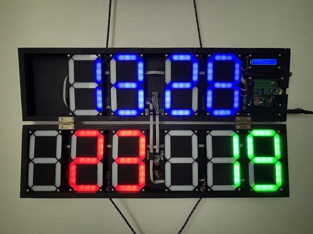
I will take you through the design process, from the initial idea to the final product, and there may be some self-deprecating comments along the way.
Product List
Electronic Components
- Arduino Nano Every development board
-
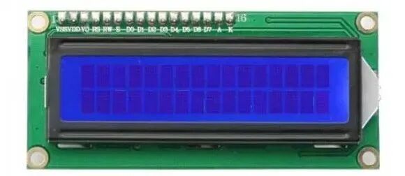
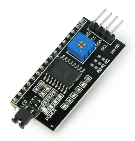
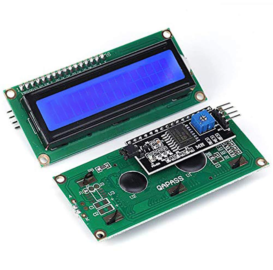
16×2 character LCD screen with I2C adapter
- DS3231 real-time clock module
- RF 433MHz wireless receiver/transmitter
- Rotary encoder
- 12V DC power supply with 5.5mm plug connection
- LED strip, 2835 diode type, tri-color
- 74HC595 shift register chip (10 pieces)
- ULN2003 Darlington transistor array chip (10 pieces)
- DIP16 socket (20 pieces)
- 100nF/50V ceramic capacitors (10 pieces)
- 1k, 2k resistors
- IDC 6-pin angled connectors/sockets + connectors (10 pieces)
- IDC flat cable
- ARK 2-pin connectors (3 pieces)
- Prototype board
- Angled pins and sockets
- HC-05 Bluetooth module (optional)
Mechanical Parts
- M2/M3/M4 nuts, bolts, and washers
- Translucent diffusing acrylic/plexiglass, 2mm thickness for 7-segment display
- PLA filament for 3D printing
- Plywood or HDF board, 3mm thickness for scoreboard casing
- 14x20mm wooden strips for scoreboard casing frame
- Black spray paint, 400ml can
- Hinges (2 pieces) + a few wood screws
Implementation Steps
Step 1: Assumptions and Requirements
Before I dive into the design and implementation process, I should describe the assumptions and requirements that the scoreboard should meet.
Functional Requirements:
- Maintain 3-digit scores for two teams
- Display game time and real-time clock
- Can be controlled during the game via a small remote control, range 20-30 meters
- Can run various types of games (score only, timed quarters, time alarms)
- Has a control and configuration menu system
Technical Requirements:
- Use Arduino as the microcontroller
- Utilize large 7-segment displays to show scores and time
- Include an LCD screen for menu navigation
- Include a rotary encoder with buttons for user input
Design Requirements:
- Relatively compact and easy to transport
- Clear and bright display visible from a distance and in bright indoor lighting
- Allows further flexibility in the number of 7-segment displays used
- Component costs are reasonable, with a focus on economy
- Modular for easy design, construction, testing, and changes
These assumptions and requirements form the basis for the scoreboard’s design and development. They help me make decisions on component selection, circuit design, and software functionality.
Step 2: Architecture and Top-Level Design
1. Top-Level Design
From the beginning, I knew there would be blind spots, errors, and failures. I wanted this design to allow me to learn continuously during the practical process, whether in software or hardware, solving problems with minimal cost and rework. This is why the concept of the mainboard was separated into three independent components: the mainboard (Arduino + components), power distribution, and LCD display.
One of the assumptions is to allow flexibility in the number of 7-segment displays.
You can easily imagine building a scoreboard with a full score display (2 x 3 digits) and a full time display (4 digits), which would require ten 7-segment displays. But reconstructing (or building the next version) the scoreboard into a “score only” version should be just as easy; you would only need 6 digits or even fewer, say 2 x 2 digits without a time display.
This is why I designed the digital displays to use a chain topology connection instead of a star topology, where each digit must connect to the mainboard. Any changes would require redesigning the mainboard PCB, which I wanted to avoid. The chain topology connection of the seven-segment displays allows for easy expansion or reduction of the number of displays.
2. Choosing Arduino Nano Every
I started with the regular Arduino Nano for some initial proof-of-concept designs, but soon found it couldn’t handle the large number of Arduino libraries and source code required for multiple hardware components (like the LCD screen, radio, and clock). There were many other libraries planned for use, such as in-game state machines, non-blocking timers, or button debouncing.
I ultimately chose the Arduino Nano Every, mainly because it offers expanded memory compared to the Arduino Nano.Arduino Nano Every has 6 KB of memory, while the regular Arduino Nano only has 2 KB. Fortunately, the two boards have almost the same footprint and pin configuration, so they can be easily swapped during prototyping or when checking individual components.
3. Choosing Arduino Mainboard Components
Choosing other mainboard components is relatively simple compared to the Arduino type itself.
I chose standard components like the DS3231 real-time clock with battery support or the 16×2 LCD screen with I2C adapter, as there are plenty of examples and tutorials online to help you get started.
Choosing the LCD screen is a good choice because it supports the forntoh/LcdMenu library, which is very convenient for menu operations and has out-of-the-box support for rotary encoders.
Make sure your LCD display comes with an I2C adapter – this will save you the headache of connecting the “raw” LCD display to the Arduino. Connecting the two using the I2C protocol is very simple, just providing VCC/GND and SDA/SCL, so only 4 wires are needed.
I couldn’t avoid the troubles caused by being cheap on components. For the radio module, I initially chose some very cheap ones, like this one, which only cost a few dollars:
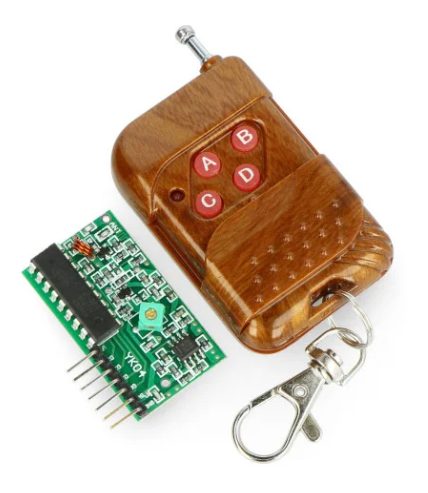
But it wasn’t stable enough, and it wasn’t reliable at the normal expected distance of 10-15 meters between you and the scoreboard on the basketball court. So I chose more expensive components (QIACHIP RF 433 MHz transmitter and receiver), which turned out to be very reliable and stable.
The real-time clock is also a good choice. The DS3231, widely used in Arduino, supports the I2C protocol, saving Arduino pins, and is very easy to operate using existing libraries.
4. Choosing LEDs
I chose simpler and cheaper components for the LEDs – LED strips:
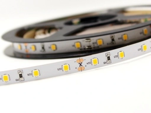
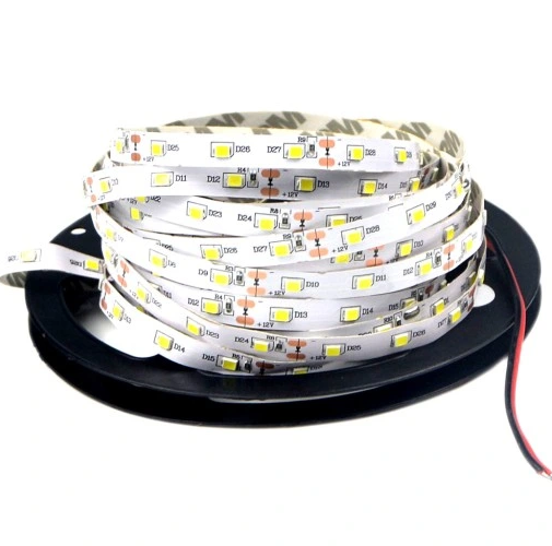
They can be easily cut into shorter segments, with at least three diodes every 5 centimeters. They come with built-in LED resistors, making it easy to solder them to the power supply. To power these LED strips, we need a 12V voltage, but the Arduino cannot provide 12V through its output pins since its operating voltage is only 5V, so we need something else to provide 12V.
We also need to solve another problem: the Arduino has 22 output digital pins. We need… 70 of them 🙂
The scoreboard displays ten digits: 4 for time, 6 for scores. Each digit (7-segment display) consists of 7 segments that need to be managed individually.This means the Arduino needs 70 separate control points to turn the lights on and off.
5. Choosing 7-Segment LED Drivers (74HC595 + ULN2003)
We need at least 70 digital output pins to control each of the 70 LED segments of the digits.Compared to the number of digital pins available on the Arduino Nano Every (assuming 22 pins are available), this far exceeds its processing capability.
We also have to let the Arduino communicate with the radio, clock, LCD screen, and almost every component consumes 2-3 pins. This reduces the number of output pins available to light up the 7-segment digits.
The simplest way to “multiply” the number of Arduino output pins is to use shift registers like the 74HC595. Using the 74HC595 shift register allows you to control multiple 7-segment displays with fewer Arduino pins.
The 74HC595 chip itself is fast, but it cannot handle the large current required to power the LED strips. Remember: it still uses the same logic voltage as the Arduino itself, which is 5V.
More importantly: the maximum current for each 74HC595 output pin is 35mA. The maximum current that can be passed through the VCC or GND pin of the 74HC595 is 70mA.This means you cannot draw 35mA from all 8 output pins simultaneously.
Back to the LED strips, according to the datasheet, these SMD 2835 EPISTAR LED strips consist of 60 diodes per meter. They are powered by a 12V DC supply, consuming 4.8W of power per meter, with a current of 0.4A.
Now, for the scoreboard, for each 7-segment digit, we need to cut out 7 segments of short pieces with 3 diodes from the longer LED strip.
Quick calculation for a single 7-segment digit:
- 7 x 3 diodes = 21 diodes
- 60 diodes consume 0.4A
- 21 diodes consume 0.14A
To power a single 7-segment digit, we need 12V and 0.14A. We have 10 digits, so in the worst case, displaying the digit ‘8’ (i.e., all LEDs on), we need a maximum current of about 1.4A.
This is where the ULN2003 microchip comes into play.
From the ULN2003 specifications, we can learn:
- Maximum load per output pin: 500mA (600mA instantaneous)
- Maximum output voltage: 50V
- Logic voltage: 5V
- Can connect outputs to multiply power
It seems capable of controlling powerful LEDs, stepper motors, and DC motors. The ULN2003 Darlington transistor array can support the necessary current and voltage required to drive the LED segments, protecting the Arduino and 74HC595 from significant overload and damage.
Step 3: Designing Electronic Components and PCB
For the electronic components, I used KiCad to create the schematic and design the PCB layout.
To reduce my chances of failure, I conducted many small Arduino setups before proposing this final design, learning how to connect each component individually and ensuring my breadboard prototype worked reliably and stably for each component.
The schematic of the mainboard looks like this:
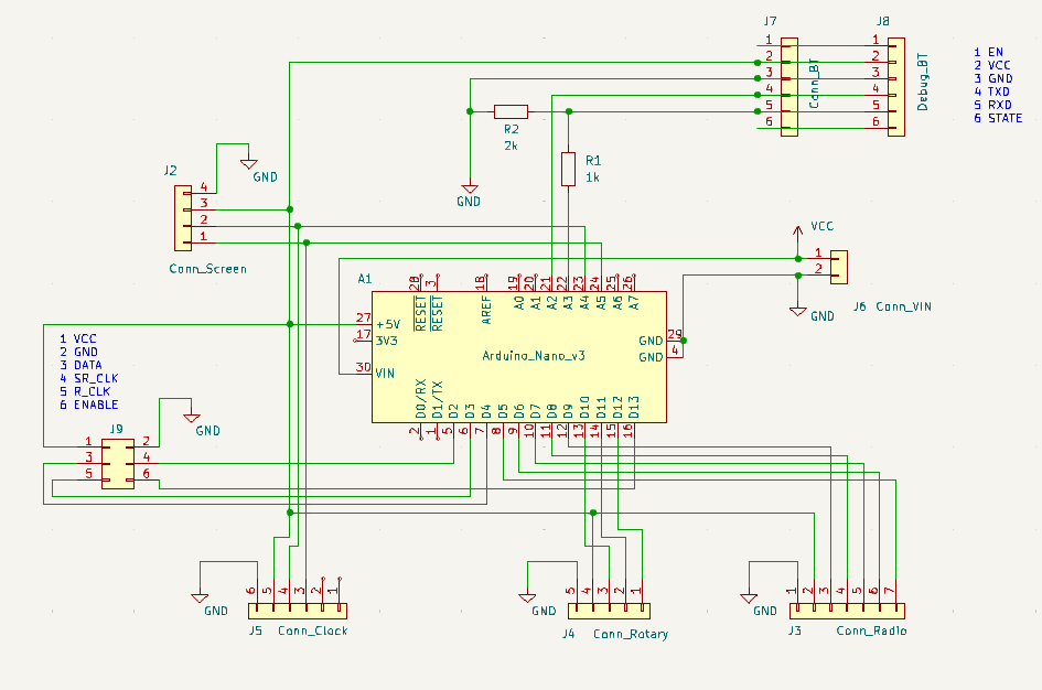
Mainboard Schematic
I did some experiments with Bluetooth LE connections and added a connector for the Bluetooth HC-05 module, just to get the mainboard and Arduino hardware ready.
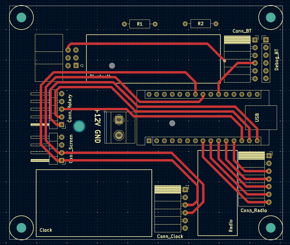
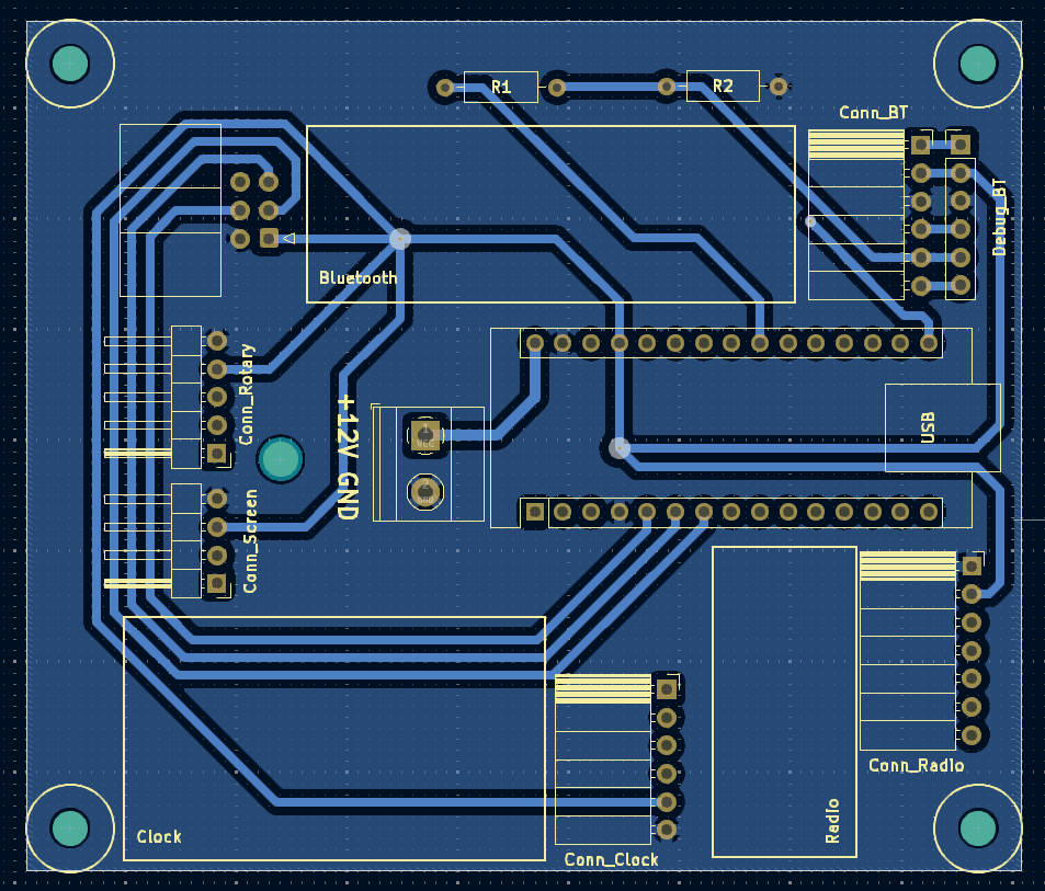 Mainboard PCB Design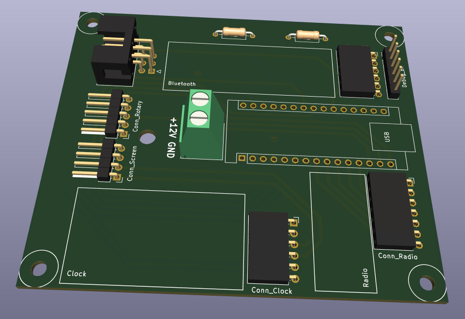
Mainboard PCB Rendering
The electronic design of the 7-segment LED driver is based on the combination operation of the 74HC595 shift register and the ULN2003 transistor array. The 74HC595 receives serial data from the Arduino and triggers the input switches of the ULN2003 through its outputs, then the ULN2003 outputs 12V to the corresponding LED segments of the 7-segment digits.
This custom 7-segment LED driver receives input signals from the Arduino via the Digit_IN connector. The Digit_OUT connector allows daisy chaining multiple LED drivers.
Some input signals from the 74HC595 shift register simply pass downstream to the LED driver chain (like serial clock or register clock, of course, VCC and GND), as these signals are common to all LED drivers, driving the continuous digits on the scoreboard.
Each 74HC595 chip has a QH’ output pin, which serves as the output of the shift register, i.e., passing serial data to the next 74HC595 chip in the chain if you plan to daisy chain multiple of these chips. I do plan to do so 🙂
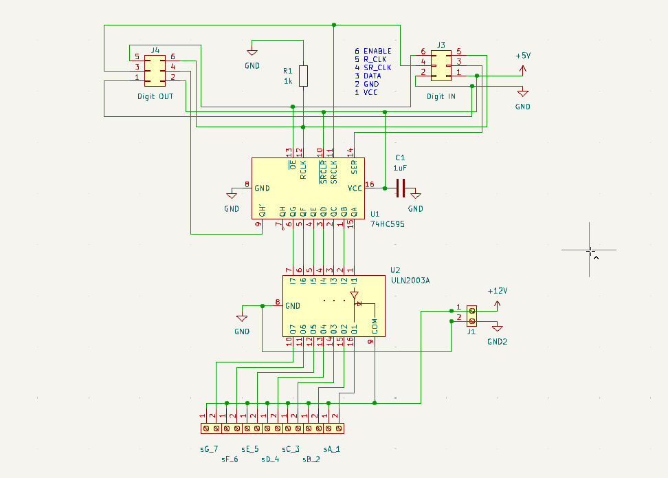 7-Segment LED Driver Schematic
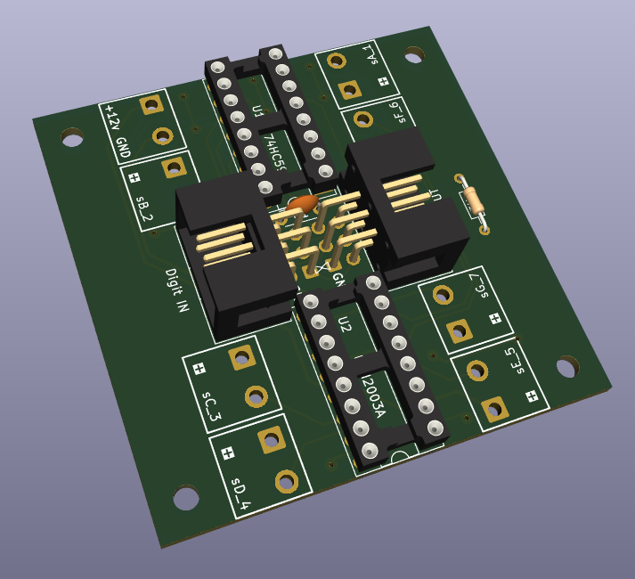 7-Segment LED Driver PCB Rendering
Once the PCB design is complete (praying there are no missing grounds…), I sent them to PCBWay for manufacturing. I just want to say, these guys are amazing. The boards arrived quickly and are of top-notch quality. Additionally, they have a cool online viewer that allows you to check your design before manufacturing. PCBWay also ensures your ideas meet manufacturing standards before the PCB goes into production, so it’s nice to know there’s a second line of defense before making mistakes.
Step 4: Software (PlatformIO and Arduino)
With the hardware resolved, it’s time to write some code. I used PlatformIO, which is a very suitable IDE for Arduino development (and other platforms). In my opinion, it is more organized and stable than the standard Arduino IDE.
The main operations include:
- Handling menu navigation via the rotary encoder and LCD screen
- Managing and setting the time of the real-time clock
- Controlling state (machine) logic
- Reading input from the RF 433MHz remote control (score up/down in the game)
- Updating the 7-segment displays to turn on/off LED segments by pushing bit sequences to the 74HC595 shift register
Below is how to send on/off bits to the 74HC595 shift register for the seven-segment display.
// Arduino pins to control shift registers#define PIN_SHIFT_REGISTER_CLOCK 2#define PIN_SHIFT_REGISTER_LATCH 3#define PIN_SHIFT_REGISTER_DATA 4...// global variables to store characters to be displayedconst byte MAX_DISPLAYS = 10; // maximum number of 7-segment displayschar g_values[MAX_DISPLAYS]; // N single digits to be displayedbyte g_registerArray[MAX_DISPLAYS]; // array of numbers to pass to shift registers...// 7 segments of the digitconst byte __ = 0;const byte A_ = 1;const byte B_ = 2;const byte C_ = 4;const byte D_ = 8;const byte E_ = 16;const byte F_ = 32;const byte G_ = 64;// 0-9 digits composed of individual segments of the 7-segment digitCHARACTERS[0] = A_ + B_ + C_ + D_ + E_ + F_ + __; // '0'CHARACTERS[1] = __ + B_ + C_ + __ + __ + __ + __; // '1'CHARACTERS[2] = A_ + B_ + __ + D_ + E_ + __ + G_; // '2'CHARACTERS[3] = A_ + B_ + C_ + D_ + __ + __ + G_; // '3'CHARACTERS[4] = __ + B_ + C_ + __ + __ + F_ + G_; // '4'CHARACTERS[5] = A_ + __ + C_ + D_ + __ + F_ + G_; // '5'CHARACTERS[6] = A_ + __ + C_ + D_ + E_ + F_ + G_; // '6'CHARACTERS[7] = A_ + B_ + C_ + __ + __ + __ + __; // '7'CHARACTERS[8] = A_ + B_ + C_ + D_ + E_ + F_ + G_; // '8'CHARACTERS[9] = A_ + B_ + C_ + D_ + __ + F_ + G_; // '9'...void sendSerialData(byte registerCount, byte *pValueArray) {digitalWrite(PIN_SHIFT_REGISTER_LATCH, LOW);for (byte reg = registerCount; reg > 0; reg--) {byte value = pValueArray[reg - 1];for (byte bitMask = 128; bitMask > 0; bitMask >>= 1) {digitalWrite(PIN_SHIFT_REGISTER_CLOCK, LOW);digitalWrite(PIN_SHIFT_REGISTER_DATA, value & bitMask ? HIGH : LOW);digitalWrite(PIN_SHIFT_REGISTER_CLOCK, HIGH);}}digitalWrite(PIN_SHIFT_REGISTER_LATCH, HIGH);}void pushShiftRegisters() {for (byte i = 0; i < MAX_DISPLAYS; i++) {if (g_values[i] != -1)g_registerArray[i] = CHARACTERS[g_values[i]];elseg_registerArray[i] = 0;}sendSerialData(MAX_DISPLAYS, g_registerArray);}Step 5: Assembly and Integration
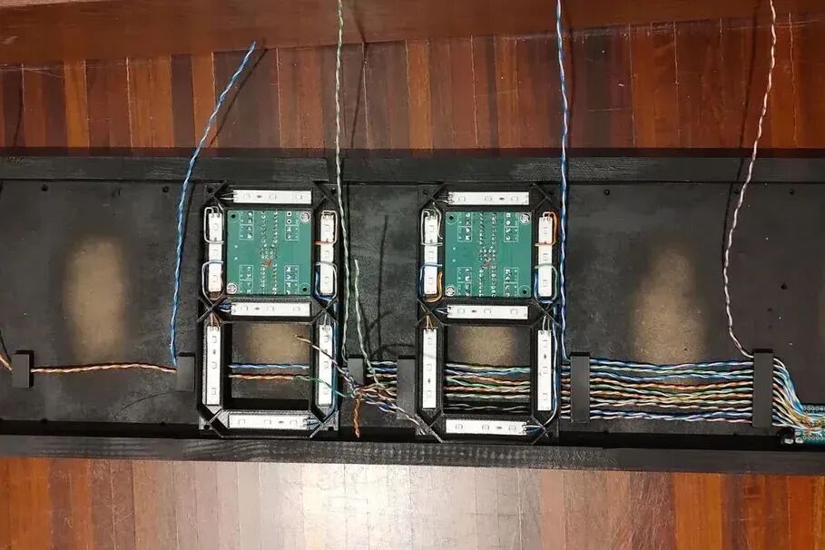
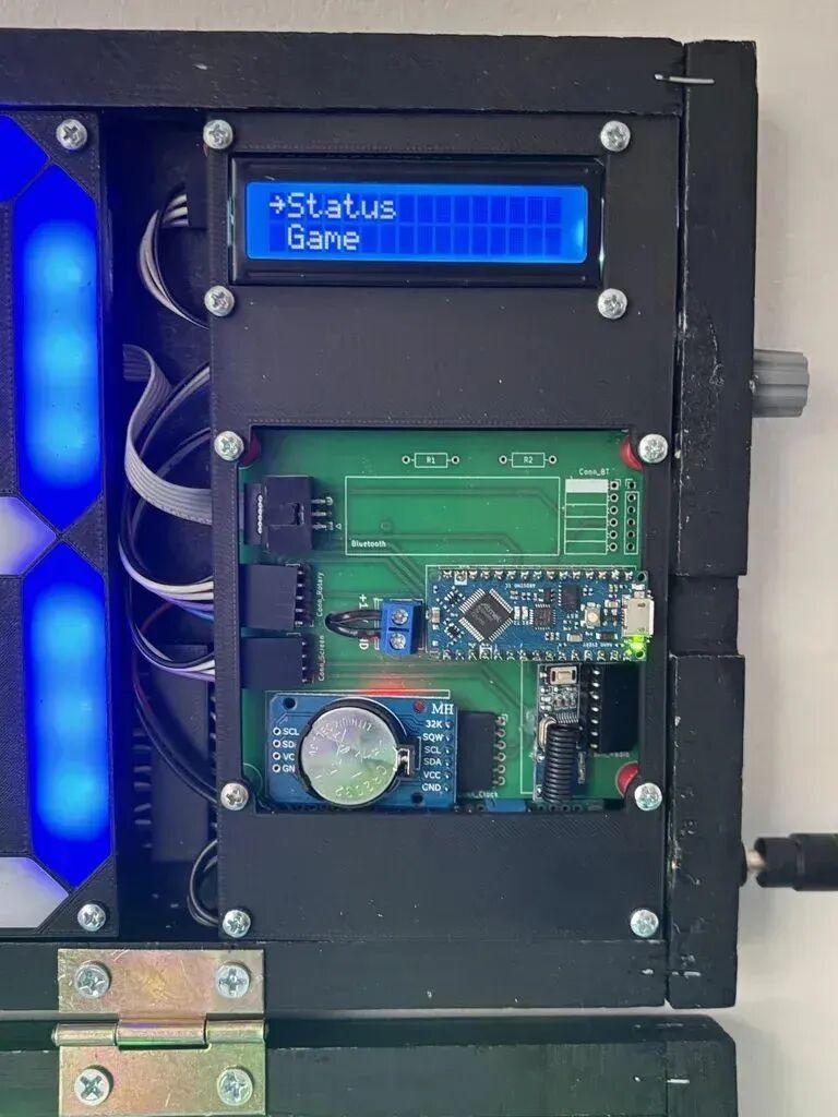
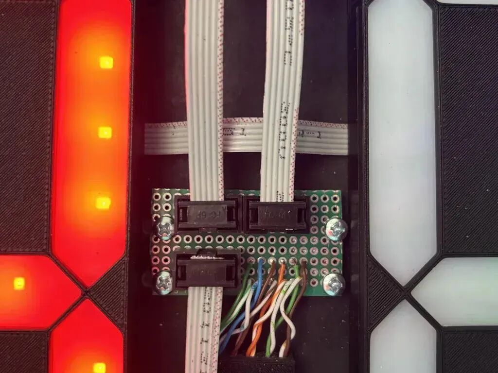
Here are some pictures of the working integration part. The final scoreboard casing is 39x70cm, weighing exactly 2.7kg + 300g for the 12V power supply. In total, an extra 3kg to carry to the basketball court with my game gear. With hinges, it folds nicely to fit in the car trunk along with my game equipment.
Step 6: Future
Here are some ideas for future improvements:
-
Battery Power:Since power outlets on the basketball court are not always conveniently found, a set of 18650 batteries should provide 2 hours of battery operation.
-
Bluetooth Connection and Mobile App Control:Now that it’s the 21st century, everything should have a mobile app! This is where the Bluetooth module comes into play. The mainboard PCB is already prepared to accommodate the HC-05 BT module for out-of-the-box connection with Arduino.
-
Sound Effects:Imagine the beeping sound at the end of the game or the horn sound during breaks!
Step 7: Android Mobile App
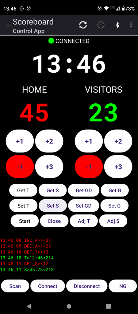
With a background in software development, and with a little help from AI-assisted Android Studio, I happily built an Android mobile app to configure the scoreboard, start and stop games, adjust scores and timers, etc. The app interface is still a work in progress, but it does reduce the need to touch the scoreboard, except for connecting the power to the wall.
This is a whole new learning area for me, mainly mastering Bluetooth LE connections and updating my Android app design patterns.
This project showcases the complete development process from concept design to finished product manufacturing, involving multiple professional fields such as electronic engineering, software development, mechanical design, PCB manufacturing, etc., making it an excellent comprehensive DIY project case.
After seeing this project, do you also want to try making one? The most valuable aspect of this scoreboard project is that the author generously shares the complete technical details and lessons learned. From the choice of Arduino Nano Every to the clever combination of 74HC595 + ULN2003; from the star topology of PCB design to the precise fit of 3D printing… every technical decision is backed by thoughtful consideration.
If you want to give it a try, you can purchase the components based on the list provided by the author. Here is the original project link: https://www.instructables.com/Radio-Controlled-Electronic-Basketball-Scoreboard/, feel free to click to learn more.

Click “Read the original text” for more project details