Follow+Star PublicNumber, don’t miss the wonderful content

Source | One Linux
Microcomputer Bus Address
Address Bus:
-
Baike Baidu Explanation: The address bus (Address Bus; also known as: location bus) is a part of the computer bus, used by the CPU or units with DMA capability to communicate the physical addresses of the memory components/locations they want to access (read/write). -
Address Bus = the range of memory that the CPU can access: To explain the address bus with an example: A 32-bit Windows 7 system installed recognizes only 3.8G of the 8G memory stick, while a 64-bit version can recognize the full 8G. 32-bit can represent/access 4,294,967,296 bits
| kbit——mbit——gbit | Difference 1024 |
|---|---|
| bit | 4,294,967,296 |
| kbit | 4,194,304 K |
| mbit | 4,096 M |
| gbit | 4 G |
-
Address Bus = the data transmitted by the address bus is what the CPU uses to find external memory units. If the CPU has 8 address lines, each transmitting 0 or 1, then the range of data transmitted is <span>00000000~ 11111111</span>, each value corresponds to a memory unit in memory, so it can find the memory unit numbered<span>00000000~ 11111111</span>. If the transmitted data is<span>00110011</span>, then it will find the memory unit numbered<span>00110011</span>, if the transmitted data is<span>10110111</span>, then it will find the memory unit numbered<span>10110111</span>. The CPU cannot find numbers outside the range of<span>[00000000,11111111]</span>, for example, it cannot find the memory unit numbered<span>100000000</span>. Addressing capability is the calculation of how many memory units the CPU can find,<span>00000000~11111111</span>has a total of 256, and the size of one memory unit is 1 byte, so the total size of these 256 memory units is 256 bytes. -
The CPU specifies memory units through the address bus. -
**==The address bus determines the maximum memory space size that the CPU can access==.eg: 10 address lines can access the maximum memory of <span>1024</span>** (2 to the power of 10) bits of binary data (1B) -
The address bus is the sum of the number of address lines. If the CPU’s address bus width is 32 bits, then the CPU’s addressing range is 4G (2 to the power of 32 bits), so it supports a maximum of 4G memory. -
For example, in the phenomenon we mentioned above: A 32-bit Windows 7 system installed recognizes only 3.8G of the 8G memory stick, while a 64-bit version can recognize the full 8G. The 32-bit operating system allows the CPU to access a range of 2^32 bits, which equals 4194304 kbit, or 4096 Mbit, which equals 4G. The Raspberry Pi is also 32-bit, with 1G of memory, but it can only access 949M, with the rest being used for other purposes.
Data Bus:
-
The CPU addresses through the address bus, and then exchanges information with external devices via the data bus. -
It is the channel for data transfer between the CPU and memory or other devices. -
The width of the data bus determines the speed of data transfer between the CPU and the outside world. -
Each transmission line can only transmit 1 bit of binary data at a time. For example, 8 data lines can transmit an 8-bit binary data (i.e., one byte) at once. -
The data bus is the sum of the number of data lines, and the number of bits in the data bus determines how much information the CPU can exchange in a single communication.
The impact of data bus width on CPU performance:
-
First, bus speed (i.e., the CPU’s main frequency, one of the performance indicators of the CPU) determines the speed at which the CPU exchanges information with peripherals. -
Secondly, the width of the data bus is also one of the parameters representing CPU performance (typically, when we say “64-bit CPU”, we refer to the width of the CPU’s data bus being 64 bits). For example, a CPU with a 64-bit data bus can retrieve 64 bits of data at once, while a CPU with an 8-bit data bus can only retrieve 8 bits of data at a time. At the same frequency, a CPU with an 8-bit data bus must retrieve data 8 times to match the data amount retrieved by a 64-bit data bus at once, meaning the performance difference in data retrieval is 8 times. Moreover, typically, the bit width of registers within the CPU matches the width of the data bus, so in terms of data processing, a 64-bit CPU is much faster than an 8-bit CPU. -
The number of address bus bits and the data bus can differ (a typical example is the 8051 microcontroller), but they are generally the same. A 16-bit machine has 16 data lines and 20 address lines, allowing access to 1M (2 to the power of 20), while a 32-bit machine has 32 data lines and 32 address lines, allowing access to 4G (2 to the power of 32), and a 64-bit machine indeed has 64 data lines.
Physical Address (PA)
-
Baike Baidu Explanation:The physical address of the network card corresponds to the actual address of the memory unit stored in the storage, which is called the physical address, corresponding to the logical address. The physical address of the network card is usually written into the network card’s EPROM (a type of flash memory chip, usually erasable through programming) by the network card manufacturer, and it stores the address that identifies the computer sending the data and the receiving host during data transmission.
-
The physical address mentioned here refers to the actual address of the memory unit in memory, not the address of other electronic components connected via external buses! **==The physical address is relatively easy to understand; it is simply the numbering of each memory unit in memory==**. This numbering is arranged sequentially, and the size of the physical address determines how many memory units there are in memory, with the size of the physical address determined by the width of the address bus! Physical address is the actual or absolute address of the hardware
Virtual Address (VA)
-
The virtual address is the logical address used by programs running in Windows when in 386 protected mode, which is based on an algorithm ==logical address== (software-level address: fake address)is called the virtual address==, similar to segmented addresses in real address mode. The virtual address can also be written in the form of “segment: offset”, where the segment refers to the segment selector. Linux does not have various protection modes and originally uses virtual addresses. -
The virtual address is a concept under the CPU’s protected mode; the protected mode is an operational mode of x86 compatible CPUs from the 80286 series and later. After the CPU has booted the operating system kernel, the operating system kernel enters a CPU protected mode, also known as virtual memory management. After this, programs run in virtual memory, and all addresses in virtual memory are indirect. Thus, you may sometimes see a virtual address corresponding to different physical addresses, for example, the entry virtual address of the call function in process A is 0x001, and in process B it is also 0x001, but they correspond to different physical addresses. The operating system adopts this memory management method. -
It prevents programs from writing data to physical addresses, causing unnecessary problems. For example, if the physical address of process A is known, writing data to that address would cause issues in process A. Programs running in virtual memory never know the physical address of the memory segment they are in! Now, even if one knows the physical address of other processes while the operating system is running in protected mode, it is not allowed to write to it! However, it is possible to obtain full control over the virtual address space of that process and write specified data through backdoor functions left by the operating system. -
Virtual memory management adopts a method of “robbing Peter to pay Paul”, so the memory in virtual memory can be much larger than physical memory. Before entering virtual mode, both the CPU and Bootloader (the BootLoader runs before the operating system kernel, initializing hardware devices and establishing a memory space mapping to prepare the software and hardware environment for the operating system kernel) operate in real mode, directly accessing physical addresses! Virtual memory also has paging management, which ensures that there is no memory fragmentation. After the operating system kernel initializes the paging table in memory, the CPU’s paging flag will be set, which is for the MMU to observe! -
MMUstands for Memory Management Unit, which is the ==control line used in the central processing unit (CPU) to manage virtual and physical memory, and is responsible for mapping virtual addresses to physical addresses, as well as providing hardware mechanisms for memory access authorization in multi-user, multi-process operating systems==. It has two main functions: address translation and memory protection. ==The MMU translates virtual addresses into physical addresses.==
Blog post about various address introductions:
Physical address, virtual address, bus address, differences between physical address and bus address
Page Table (MMU Unit)
Paging Management: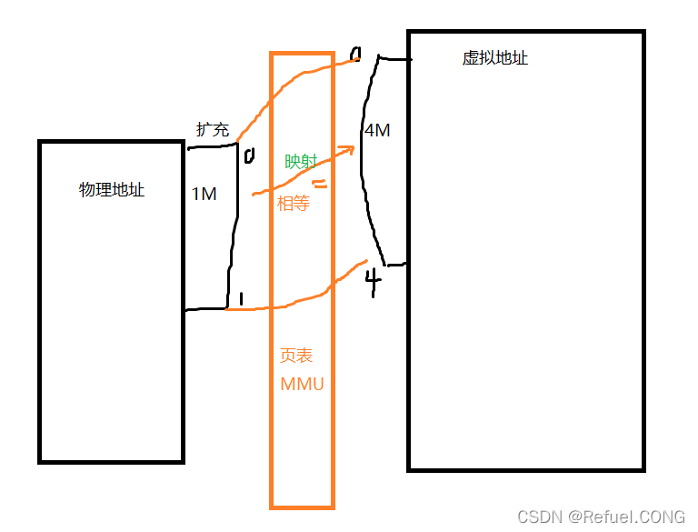
-
Memory paging is essentially what we refer to as 4G space, where all memory is divided by the operating system kernel into pages of 4G. When our program runs, it is loaded into this 4G space in memory. However, it is said to have 4G, but there is not actually a full 4G space available; a small portion of the 4G space is mapped to physical memory, some may be mapped to files on the hard disk (fopen), and some may not be mapped at all. Additionally, a portion of the memory will be divided into stack and heap, with large portions of memory remaining unmapped. Similarly, physical memory is also paged to create a mapping relationship with virtual memory. The algorithm (page table) that maps virtual addresses to physical addresses determines where the virtual address maps to the physical address, and the page table is managed by the MMU (paging memory management unit); after designing the page table, the MMU executes the mapping of virtual addresses to physical addresses.
-
In reality, there is only 3G of user space. If your memory is 4G, then 1G is allocated for the operating system kernel. The so-called 4G space gives the illusion that each process has 4G of usable space! Here we refer to the method of “robbing Peter to pay Paul”. When our program is loaded into the 4G space, it cannot actually utilize the entire 4G space; large portions of memory remain idle. When other programs are loaded in and find insufficient memory, they can borrow the idle portions from the 4G space of other programs for their use. Conversely, when this process runs out of memory, it can borrow idle space from other processes.
-
When we need to operate on a physical address, such as when an if statement needs to make different jumps based on the CPU’s status register, we must know its physical address. There is an electronic component in memory called the MMU, which is responsible for querying the physical address corresponding to the virtual address from the memory mapping table initialized by the operating system and converting it. For example,
mov 0x4h8is a virtual address. When we need to write data to this virtual address, the MMU first checks whether the flag in the CPU’s paging status register is set. If it is set, the MMU captures this virtual address and queries the physical address corresponding to it in the memory mapping table initialized by the operating system, converting it into the actual physical address, then providing it to the CPU to execute the corresponding command. Conversely, when the CPU reads data from memory, for example, process A wants to read data from a certain virtual address in memory, the instruction in process A specifies a virtual address. The MMU first checks whether the flag in the CPU’s paging status register is set. If it is set, the MMU captures this virtual address and converts it to the corresponding physical address, then submits it to the CPU, which then retrieves the data from memory!
BCM2835 Chip Manual
Below is an excerpt from the Raspberry Pi chip manual: 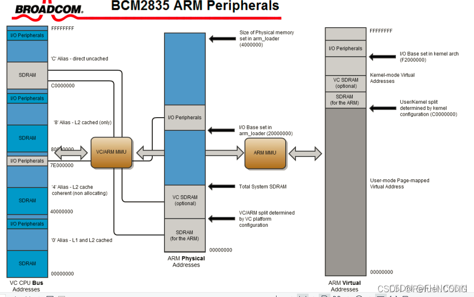
BCM2835 is the model of the Raspberry Pi 3B CPU, which uses the ARM-cortexA53 architecture. The CPU Bus is the address bus,<span>00000000~FFFFFFFF</span> is the CPU addressing range (4G). DMA is a high-speed copying unit, and the CPU can initiate DMA to directly copy data, which is a direct memory access unit. Physical Address (PA) 1G, Virtual Address (VA) 4G. If a program exceeds the physical address of 1G, does that mean it cannot run? No, it has a MMU unit that maps physical addresses to virtual addresses. The code we operate on is mostly in virtual addresses, and it has a mapping page table (mentioned above).
-
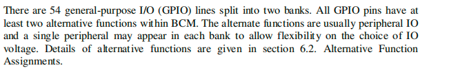
By understanding the chip manual, the Raspberry Pi GPIO has 54 general I/O GPIO lines, divided into two rows. The reserved functions are typically peripheral IO, and each bank can have one peripheral device to allow flexible selection of IO voltage.
-
GPIO has 41 registers, and all accesses are 32 bits.
-
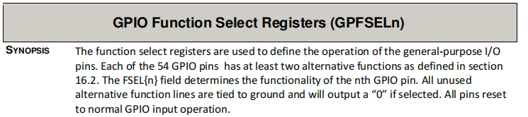
Description is the functional description of the registers. GPFSEL0 (register name)
<span>GPIO Function Select 0</span>(function selection: input or output); GPSET0 (register name)<span>GPIO Pin Output Set 0</span>(sets the IO port to 0); GPSET1 (register name)<span>GPIO Pin Output Set 1</span>(sets the IO port to 1); GPCLR0 (register name)<span>GPIO Pin Output Clear 0</span>(clears to 0). The address shown below is: bus address (not the actual physical address).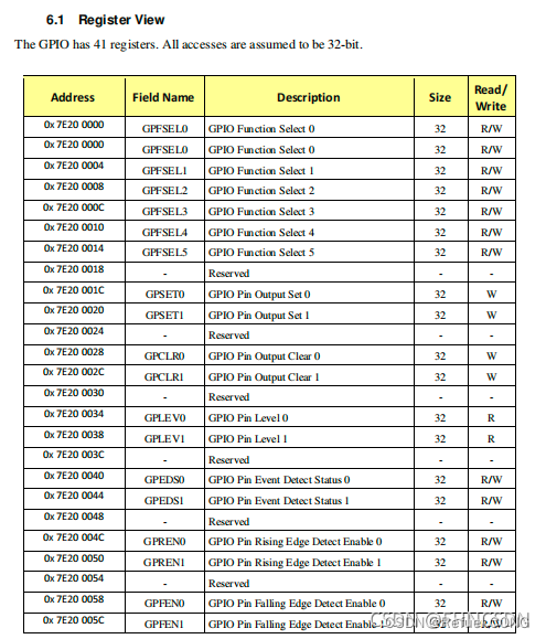
-
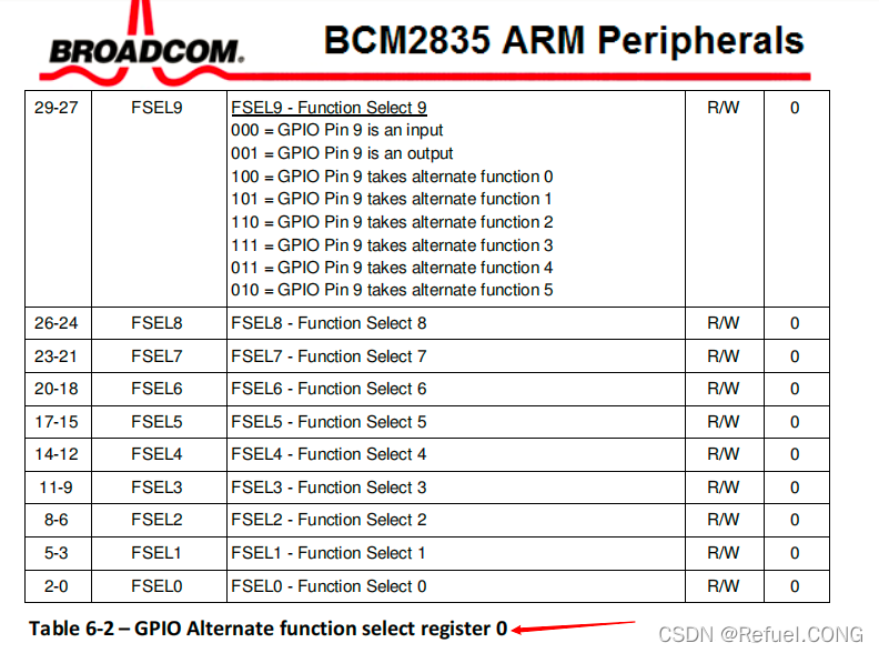
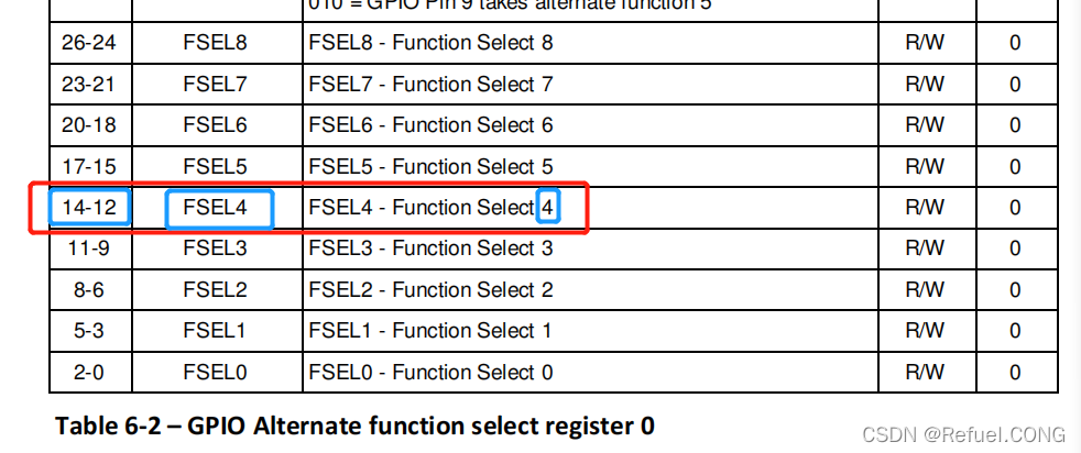
FSELn indicates GPIOn,
The image below provides an example of function selection for the ninth pin, configuring registers 29-27 to set the corresponding function. According to the image below, register 0 indicates that 0~9 uses this register 0.
-
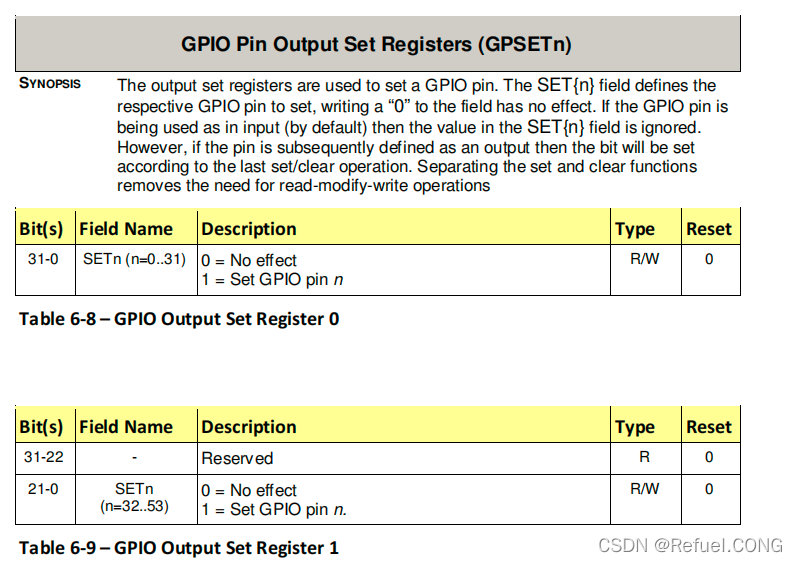
The output set register is used to set GPIO pins. The SET{n} field defines the respective GPIO pins; writing “0” to the field has no effect. If the GPIO pin is in input mode (by default), the value in the SET{n} field will be ignored. However, if the pin is subsequently defined as output, the bit will be set according to the previous set/clear operation. Separating set and clear functions eliminates the need for read-modify-write operations. GPSETn register is used to set the IO port to 1; the set4 bit sets the fourth pin, which is the fourth bit of the register.
-
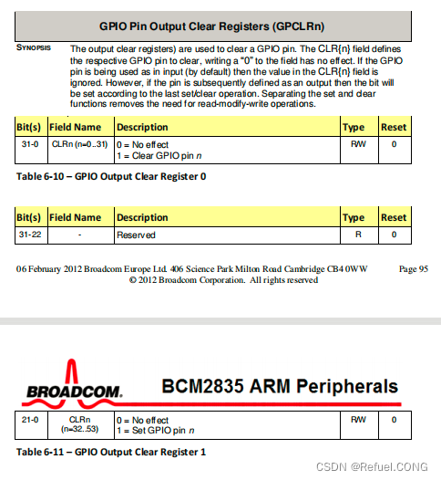
The output clear register is used to clear GPIO pins. The CLR{n} field defines which GPIO pins to clear; writing “0” to the field has no effect. If the pin is in input mode (by default), the value in the CLR{n} field is ignored. However, if the pin is subsequently defined as output, the bit will be set according to the previous set/clear operation. Separating set and clear functions eliminates the need for read-modify-write operations. GPCLRn is the clear function register.
Configure pin4 of the Raspberry Pi as an output pin:
Function selection output/input (GPIO Function Select Registers) 32 bits
14-12    001    =   GPIO Pin4 is an output
Simply set bits 14-12 of the GPFSEL0 register to 001. Shift 0x6 (which corresponds to binary 110) left by 12 bits, then invert it and AND it with GPFSEL0 to set bits 13 and 14 to 0, then OR GPFSEL0 with 0x6 (which corresponds to binary 110) shifted left by 12 bits to set bit 12 to 1.
-
You can use the copy_from_user() function in the driver code to read user input commands, and use the copy_to_user() function to let the pin feedback its current state, allowing the user to read it.
If you want to find the Raspberry Pi pin, click here
Raspberry Pi IO Control Driver Code:
ioremap, iounmap:
1. Generally, our peripherals are operated through reading and writing the registers on the device, usually including control registers, status registers, and data registers. The registers of peripherals are usually continuously addressed, and depending on the CPU architecture, there are two ways to address IO ports:
-
IO mapped (IO-mapped): A typical example is that x86 processors have a separate address space dedicated to peripherals, known as the “IO port space” or “IO address space”. The CPU can access this “IO port space” through specific instructions (like IN and OUT in x86). -
Memory mapped: CPUs with RISC instruction sets typically implement only one physical address space, with peripheral IO ports becoming part of memory. The CPU can access the IO ports of peripherals as easily as it accesses its own memory, without needing to set up specific instructions to access them. In driver development, memory mapping is generally used.
2. In the driver development process, generally speaking, the physical addresses of the IO memory resources of peripherals are known and determined by hardware design. However, the CPU does not pre-specify virtual address values for these known peripheral IO memory resources, so the driver program cannot directly access the IO memory through the physical addresses of peripherals. Instead, it must map them to the virtual address space (through page tables) before accessing these IO memory using memory instructions based on the kernel-mapped virtual addresses.
3. In the io.h header file of the Linux kernel, the ioremap() function is declared to map IO memory resources to the core virtual address space (3Gb~4GB). Of course, if it is no longer needed, it can be unmapped using iounmap(). These two functions are found in mm/ioremap.c:
Start mapping: void* ioremap(unsigned long phys_addr, unsigned long size, unsigned long flags)
// Mapping a device means associating a segment of user space address with device memory, allowing the program to read or write within the allocated address range, which actually accesses the device.
The first parameter is the starting address of the mapping.
The second parameter is the length of the mapping.
The third parameter? This depends on your hardware characteristics.
For example, if you are only mapping a 32-bit register, a length of 4 is sufficient.
(Here, the function setting registers for Raspberry Pi IO ports are all 32-bit registers, so allocating four bytes is enough.)

For example: GPFSEL0=(volatile unsigned int *)ioremap(0x3f200000,4);
   GPSET0 =(volatile unsigned int *)ioremap(0x3f20001C,4);
   GPCLR0 =(volatile unsigned int *)ioremap(0x3f200028,4);
These three lines set the addresses of the registers; the volatile keyword ensures that this instruction will not be omitted due to compiler optimization and requires reading values directly each time.
The ioremap function converts physical addresses to virtual addresses, mapping IO port registers to ordinary memory units for access.

Unmap: void iounmap(void* addr)// Cancel the IO address mapped by ioremap.
For example:
     iounmap(GPFSEL0);
        iounmap(GPSET0);
        iounmap(GPCLR0); // Release address mapping when unloading the driver.
Driver Code for Raspberry Pi IO Port 4:
#include <linux/fs.h>            //file_operations declaration
#include <linux/module.h>    //module_init  module_exit declaration
#include <linux/init.h>      //__init  __exit macro definition declaration
#include <linux/device.h>        //class  device declaration
#include <linux/uaccess.h>   //copy_from_user header file
#include <linux/types.h>     //device number  dev_t type declaration
#include <asm/io.h>          //ioremap iounmap header file

static struct class *pin4_class;
static struct device *pin4_class_dev;

static dev_t devno;                //device number
static int major =231;             //main device number
static int minor =0;               //sub-device number
static char *module_name="pin4";   //module name

volatile unsigned int* GPFSEL0 = NULL;
volatile unsigned int* GPSET0   = NULL;
volatile unsigned int* GPCLR0   = NULL;
//These three lines set the addresses of the registers
//The volatile keyword ensures that this instruction will not be omitted due to compiler optimization and requires reading values directly each time.

//led_open function
static int pin4_open(struct inode *inode,struct file *file)
{
        printk("pin4_open\n");  //Kernel print function similar to printf

        //Configure pin4 as an output pin
        *GPFSEL0 &=~(0x6 <<12); // Set bits 13 and 14 to 0
        //0x6 is 110  <<12 left-shifted by 12 bits ~inverted &ANDed
        *GPFSEL0 |=~(0x1 <<12); // Set bit 12 to 1   |ORed

        return 0;

}
//read function
static int pin4_read(struct file *file,char __user *buf,size_t count,loff_t *ppos)
{
        printk("pin4_read\n");  //Kernel print function similar to printf

        return 0;
}

//led_write function
static ssize_t pin4_write(struct file *file,const char __user *buf,size_t count, loff_t *ppos)
{
        int usercmd;
        printk("pin4_write\n");  //Kernel print function similar to printf

        //Get the value from the upper layer write function
        copy_from_user(&usercmd,buf,count); //Read the user input command into usercmd
        //Operate the io port based on the value, high or low
        if(usercmd == 1){
                printk("set 1\n");
                *GPSET0 |= 0x01 << 4;
        }
        else if(usercmd == 0){
                printk("set 0\n");
                *GPCLR0 |= 0x01 << 4;
        }
        else{
                printk("undo\n");
        }
        return 0;
}

static struct file_operations pin4_fops = {

        .owner = THIS_MODULE,
        .open  = pin4_open,
        .write = pin4_write,
        .read  = pin4_read,
};

//static limits the scope of this structure to this file only.
int __init pin4_drv_init(void)   //Real driver entry
{
        int ret;
        devno = MKDEV(major,minor);  //Create device number
        ret   = register_chrdev(major, module_name,&pin4_fops);  //Register driver, informing the kernel to add this driver to the kernel driver linked list
        pin4_class=class_create(THIS_MODULE,"myfirstdemo");//Automatically create the device under dev
        pin4_class_dev =device_create(pin4_class,NULL,devno,NULL,module_name);  //Create device file

        GPFSEL0=(volatile unsigned int *)ioremap(0x3f200000,4);
        GPSET0 =(volatile unsigned int *)ioremap(0x3f20001C,4);
        GPCLR0 =(volatile unsigned int *)ioremap(0x3f200028,4);

        printk("insmod driver pin4 success\n");
        return 0;
}

void __exit pin4_drv_exit(void)
{

        iounmap(GPFSEL0);
        iounmap(GPSET0);
        iounmap(GPCLR0); //Release address mapping when unloading the driver

        device_destroy(pin4_class,devno);
        class_destroy(pin4_class);
        unregister_chrdev(major, module_name);  //Unload driver
}
module_init(pin4_drv_init);  //Entry point; this macro will be called when the kernel loads the driver, calling the pin4_drv_init function
module_exit(pin4_drv_exit);
MODULE_LICENSE("GPL v2");
1. Set the address of the registers
Set the address of the registers, but this way of writing is problematic. As we mentioned earlier, in the kernel, the code and upper layer code access virtual addresses (VA), while now we are setting physical addresses. **==Must convert physical addresses to virtual addresses==**
//These three lines set the addresses of the registers
volatile unsigned int* GPFSEL0 = (volatile unsigned int *)0x3f200000;
volatile unsigned int* GPSET0  = (volatile unsigned int *)0x3f20001C;
volatile unsigned int* GPCLR0  = (volatile unsigned int *)0x3f200028;
//The volatile keyword ensures that this instruction will not be omitted due to compiler optimization and requires reading values directly each time.
We first initialize the addresses
volatile unsigned int* GPFSEL0 = NULL;
volatile unsigned int* GPSET0   = NULL;
volatile unsigned int* GPCLR0   = NULL;
Then assign values in int __init pin4_drv_init(void) //Real driver entry.
//Integer 11
//0xb 11 00010001
Even in hexadecimal, it is an integer; the left side isvolatile unsigned int* GPFSEL0and the right side is also forcibly converted to(volatile unsigned int*)
volatileensures that this instruction ==will not be omitted due to compiler optimization== and ==requires reading values directly each time== because it is an address I want it to be unsignedunsigned
When writing driver programs, the starting address of the IO space is 0x3f000000, plus the GPIO offset 0x2000000, so the physical address of GPIO should start from 0x3f200000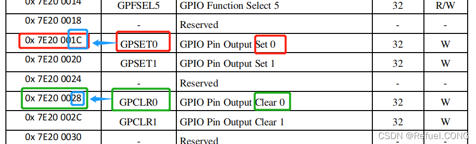 Then, based on this, perform Linux system MMU memory virtualization management, mapping to virtual addresses. The function
 ioremap is used.
//Convert physical address to virtual address, mapping IO port registers to ordinary memory units for access.
 GPFSEL0=(volatile unsigned int *)ioremap(0x3f200000,4);
 GPSET0 =(volatile unsigned int *)ioremap(0x3f20001C,4);
 GPCLR0 =(volatile unsigned int *)ioremap(0x3f200028,4);   //4 is 4 bytes
2. Configure pin4 as an output pin
 Configure pin4 as an output pin, setting bits 12-14 to 001
31 30 ······14 13 12 11 10 9 8 7 6 5 4 3 2 1
0  0  ······0  0  1  0  0  0 0 0 0 0 0 0 0
 //Configure pin4 as an output pin, setting bits 12-14 to 001
  *GPFSEL0 &=~(0x6 <<12); // Set bits 13 and 14 to 0
 //0x6 is 110  <<12 left-shifted by 12 bits ~inverted &ANDed
  *GPFSEL0 |=~(0x1 <<12); // Set bit 12 to 1   |ORed
Forget to AND and OR, click here
3. Get the value from the upper layer write function to operate the IO port, high or low
Use copy_form_user(char *buf , user_buf , count) to get the value from the upper layer write function
int usercmd;
copy_from_user(&usercmd,buf,count); //Read the user input command into usercmd

 //Operate the io port based on the value, high or low
 printk("get value\n");
        if(usercmd == 1){
                printk("set 1\n");        //Set to 1
                *GPSET0 |= 0x01 << 4;      //Use | OR operation to not affect other bits
                //Writing 1 means setting the register to 1, making bit 4 high
        }
        else if(usercmd == 0){
                printk("set 0\n");        //Clear to 0
                *GPCLR0 |= 0x01 << 4;      //Use | OR operation to not affect other bits
                //Writing 1 means clearing the register to 0, making bit 4 low
        }
        else{
                printk("undo\n");  //Prompt that this command is not supported
        }
4. Unmap
Unmap: void iounmap(void* addr);//Cancel the IO address mapped by ioremap.
void __exit pin4_drv_exit(void)
{
        iounmap(GPFSEL0);   //Unmap GPFSEL0
        iounmap(GPSET0);    //Unmap GPSET0
        iounmap(GPCLR0);   //Unmap GPCLR0

        device_destroy(pin4_class,devno);//First destroy the device
        class_destroy(pin4_class);//Then destroy the class
        unregister_chrdev(major, module_name);  //Unload driver
}
Upper layer test code:
#include<sys/types.h>
#include<sys/stat.h>
#include<fcntl.h>
#include <unistd.h>
#include<stdlib.h>
#include<stdio.h>

int main()
{
   int fd;
   int cmd;
   int data;

   fd = open("/dev/pin4",O_RDWR);
   if(fd<0){
           printf("open failed\n");
   }else{
    printf("open success\n");
   }

   printf("input command:1/0 \n 1:set pin4 high \n 0 :set pin4 low\n");
   scanf("%d",&cmd);

   printf("cmd = %d\n",cmd);
   fd = write(fd, &cmd,4); //cmd type is int, so write 4
}
Driver Unloading
After installing the driver, you can use the command: sudo rmmod + driver name (do not need to write ko) to unload the driver.
IO Port Driver Code Compilation
-
First, in the system directory /SYSTEM/linux-rpi-4.14.y, use the command:ARCH=arm CROSS_COMPILE=arm-linux-gnueabihf- KERNEL=kernel7 make modulesto compile the driver module and generate the.kofile. -
Then send the compiled driver to the Raspberry Pi: scp ./drivers/char/pin4driver.ko [email protected]:/home/pi, and then compile the upper layer code:arm-linux-gnueabihf-gcc pin4test.c -o realtest, and then send the test code to the Raspberry Pi:scp realtest [email protected]:/home/pi/ -
Then on the Raspberry Pi, use the command: insmod pin4drive.koto load the driver (thenlsmodto view this driver), -
Then use the command: sudo chmod 666 /dev/pin4to give pin4 access permissions, and you can also use mk5sum to check the value of the driver file in the virtual machine, and use this command on the Raspberry Pi to check the value of this driver file to see if they match. -
dmesgto view the kernel print information, as shown in the figure below:
-
Then run the test code, in a new window, use the command gpio readallto see that theBCMunder pin4mode is output mode, and the level is low or high (depending on the input from the upper layer code, input 0 is low, input 1 is high), here I input 0, as shown in the figure below: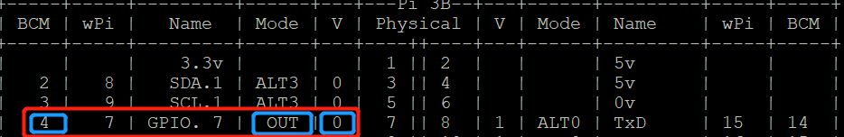
About the GPIO port address issues in the driver code:

-
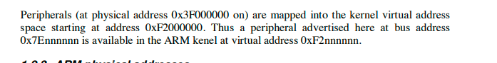
7Ennnnn means from 7E00000 to 7EFFFFFF, F2000000 is the virtual address mapped from 3F000000, then 7E00000 corresponds to F200000. The address used in the chip manual corresponds to the address that has a mapping relationship with the virtual address F200000 — 7E00000, the offset in the chip manual is the same as the physical address offset. -
According to the description in the above image, the physical address range of peripherals is m 0x3F000000 to 0x3FFFFFFF, so the actual physical address corresponding to 7E200000 should be 0x3F000000 + (7E200000-7E000000). -
GPFSEL0=(volatile unsigned int *)ioremap(0x3f200000,4); GPSET0 =(volatile unsigned int *)ioremap(0x3f20001C,4); GPCLR0 =(volatile unsigned int *)ioremap(0x3f200028,4); -
0x3f200000, 0x3f20001C, 0x3f200028 are physical addresses, the starting address of the Raspberry Pi peripheral space is 0x3f000000, and the offset of the corresponding registers is known from the chip manual, for example, the actual address of the GPFSEL0 register is 0x3f200000=0x3F000000 + (7E200000-7E000000). -
Then, through the data manual, we can see that the bus addresses of the registers related to the Raspberry Pi and the mapping virtual addresses have some corresponding relationship, leading to the offset, as shown in the image below: 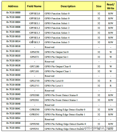
———— END ————
● Column “Embedded Tools“
● Column “Embedded Development”
● Column “Keil Tutorial”
● Selected Tutorials from the Embedded Column


Click “Read Original” to see more shares.