Due to the need for an easy-to-deploy and reliable performance antenna for portable camp radio communication, I chose a multi-band vertical radiator antenna with three ground plane radial elements. This type of antenna is reliable, stable in performance, and occupies a small footprint. The vertical ground plane antenna includes a 6-meter long radiator, capable of covering the 10-30 MHz frequency band with reasonable efficiency and a low radiation angle; it can also cover the 7 MHz band, although with reduced efficiency.01Antenna Design Features and Feed SystemThe design feature of the multi-band ground plane antenna is that it does not resonate on any amateur radio frequency band and presents a relatively high feed point impedance across all intended operating frequencies. This antenna requires a 4:1 balun and a 1:1 choke balun for feeding. Subsequently, a coaxial cable connects the entire system to the antenna matching unit and standing wave ratio (SWR) meter, ultimately connecting to the transceiver.Here, the role of the 4:1 balun is to convert the higher feed point impedance of the antenna to an impedance that is manageable by the antenna matching unit; the 1:1 choke balun is used to suppress any common mode RF current radiation that may exist on the coaxial cable, preventing this current from disrupting the ideal radiation pattern of the antenna.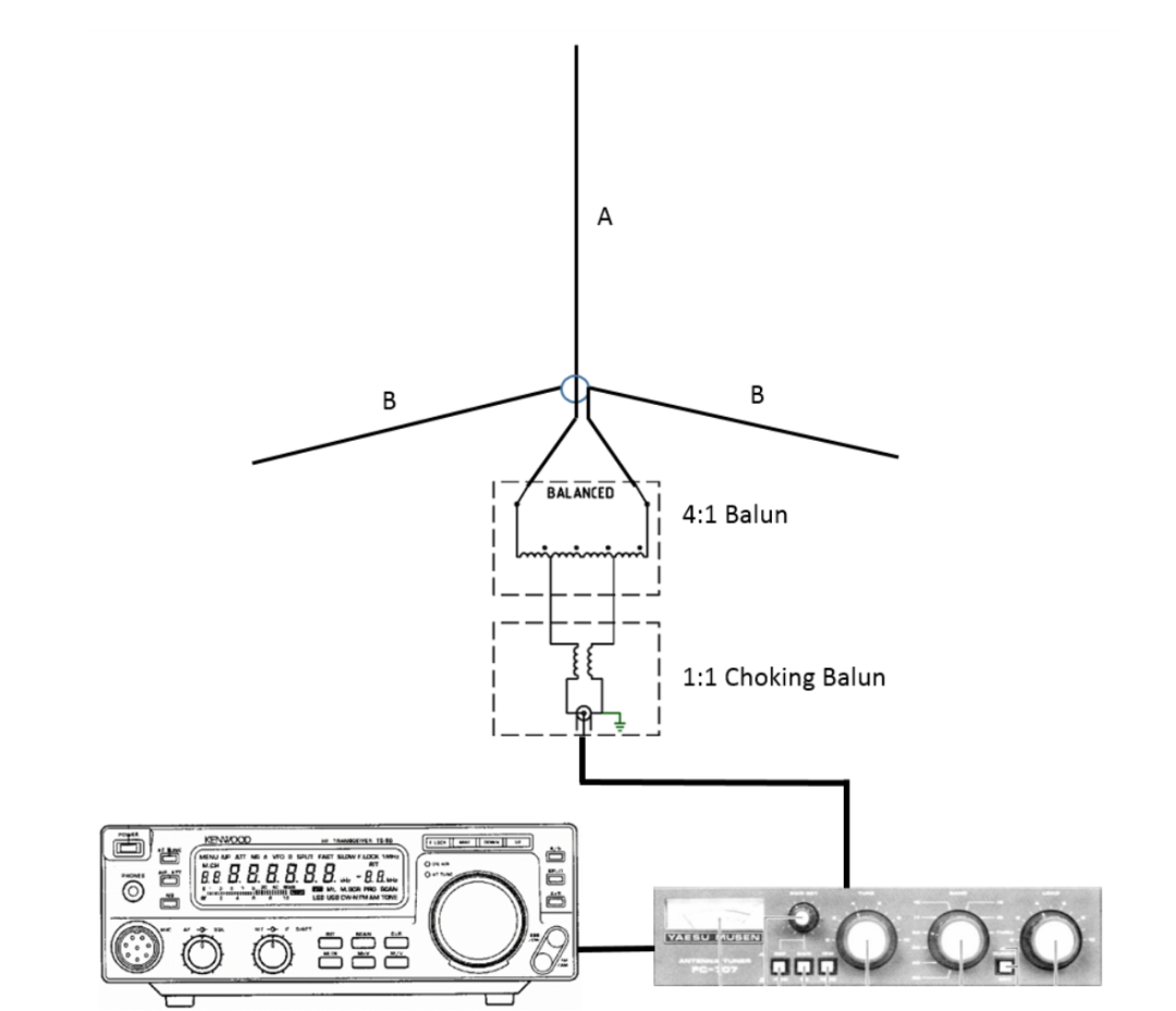 Complete Portable SetupThe image shows the antenna’s 6.0-meter vertical radiator (A), three 6.2-meter ground plane radial elements (B), a 1:1 balun hub, 50 Ohm coaxial cable, antenna matching tuner, and TS-50 model radio transceiver.02Antenna Model Prediction ResultsThe following are the prediction results from the MMANA-GAL antenna model, reflecting the load characteristics of the antenna in the 7-30 MHz high frequency (HF) band with a connection impedance of 50 Ohms. By avoiding the high reactance area near 23 MHz, all intended amateur radio frequency bands fall within the matching range of the antenna matching tuner.
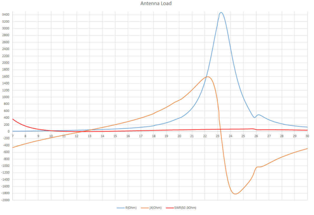 Load Characteristics Prediction of MMANA-GAL Antenna Model (Connection Impedance 50 Ohms)This model predicts the load characteristics of the antenna in the 7-30 MHz high frequency band (with a connection impedance of 50 Ohms). The vertical axis represents impedance, while the horizontal axis represents frequency (in MHz).03Structural DesignThis multi-band high frequency portable ground plane antenna has a simple structure, with the main vertical radiator length being 6 meters, made of copper wire wrapped in polyvinyl chloride (PVC) with a cross-sectional area of 0.75 square millimeters (corresponding to American wire gauge AWG 18/19). The three ground plane radial elements are also made of this material, each 6.2 meters long. Both the top of the vertical radiator and the ends of the radial elements are equipped with connection rings, and all wires are fitted with crimp connectors for connection to the balun hub.The 1:1 current balun serves as the convenient central hub for this wire-type ground plane antenna. Its size is determined by the height of the supporting structure (a 7-meter long “squid pole”, which is a multi-section telescopic antenna pole) and must meet two conditions: first, it should not present a resonant length on any amateur radio frequency band; second, its length should not be too long at the 10-meter band to avoid high angle radiation.For example, if the antenna is suspended higher in a tree, the radial elements can be tilted down to a more ideal 45-degree angle, thus providing the antenna with a better radiation angle.1:1 Current Balun (Central Hub of Wire-Type Ground Plane Antenna)The image shows that the radiator wire elements are connected to the left terminal, while the three radial elements are connected to the right terminal.
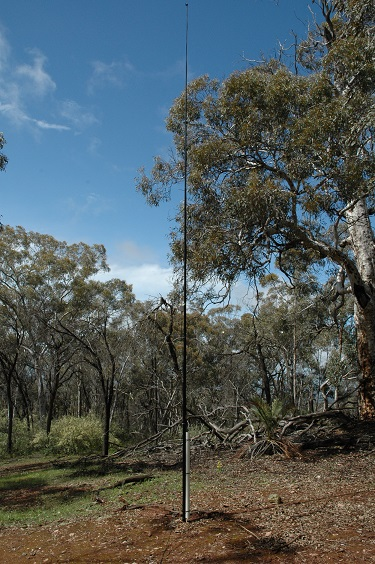 Assembled Squid Pole in the Field
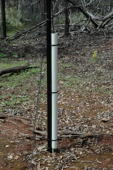 Installation Structure of the Squid Pole
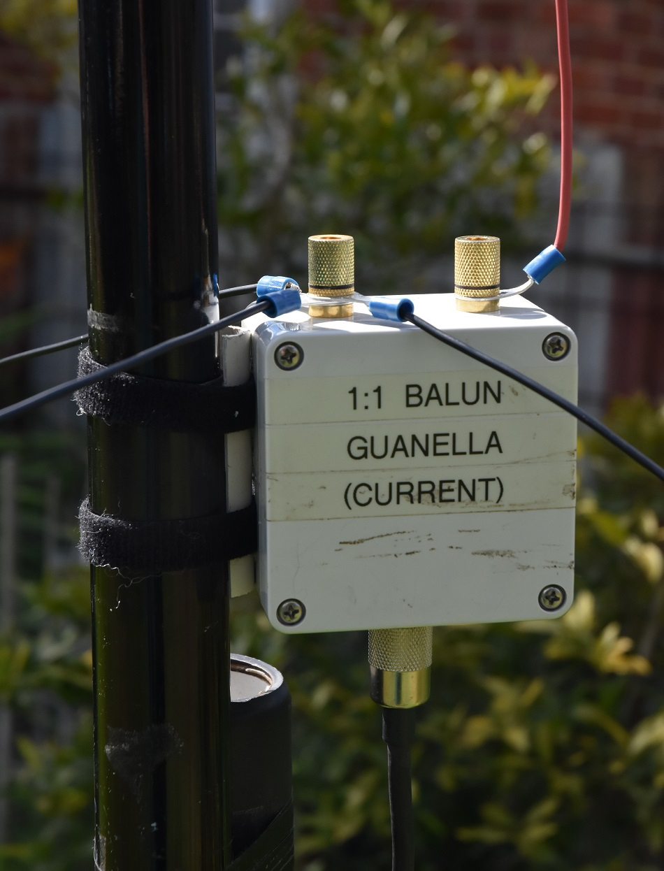 Central Balun Hub
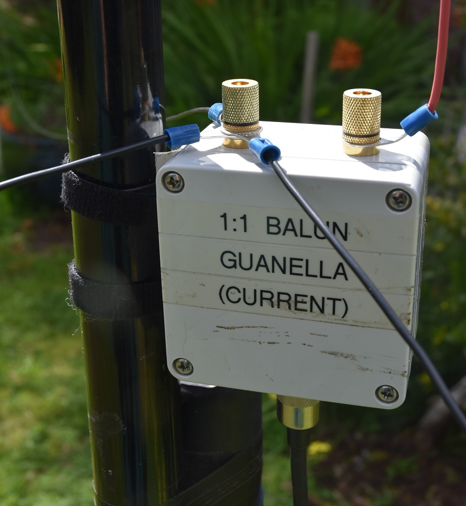 Central Balun Hub (Top View)See details related to the balun: HF feedline choke & balun – 2025090104Testing
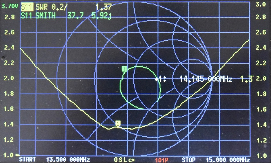 Measurement Results of the Antenna by NanoVNAThis measurement was conducted on the antenna installed on the squid pole, with the feed point approximately 2 meters above the ground.
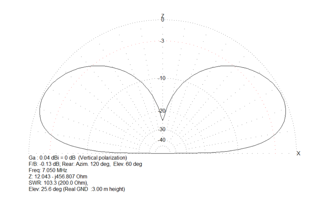 MMANA Antenna Model (40 Meter Band)This model shows that the antenna presents a uniform low-angle radiation pattern at the 40-meter band.
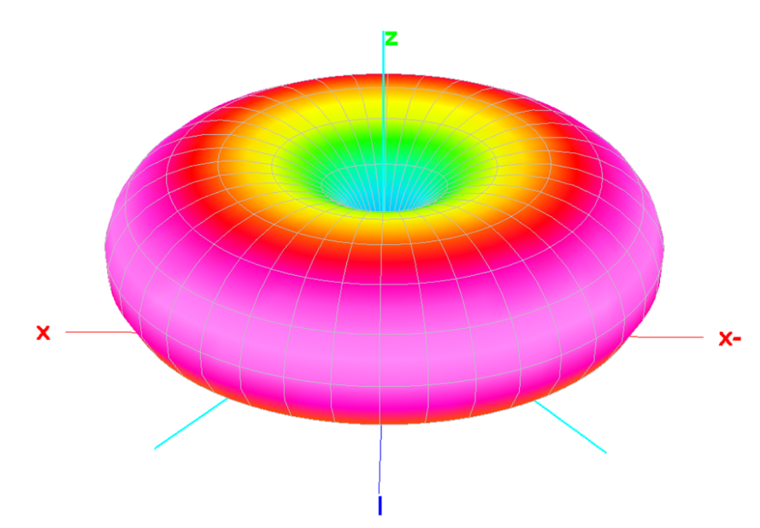 MMANA 3D Antenna Model (40 Meter Band)This 3D model shows that the antenna presents a uniform low-angle radiation pattern at the 40-meter band.
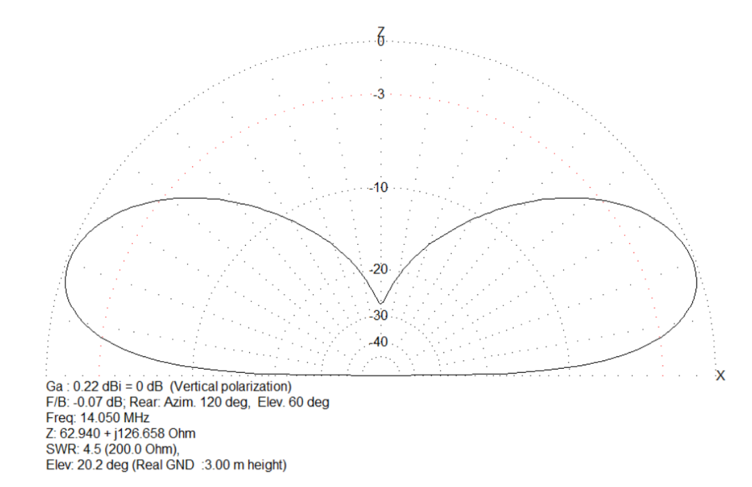 MMANA Antenna Model (30 Meter Band)This model shows that the antenna presents a uniform low-angle radiation pattern at the 30-meter band.
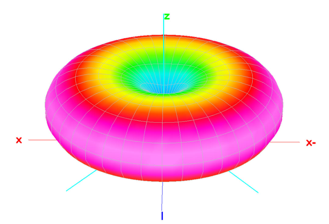 MMANA 3D Antenna Model (30 Meter Band)This 3D model shows that the antenna presents a uniform low-angle radiation pattern at the 30-meter band.
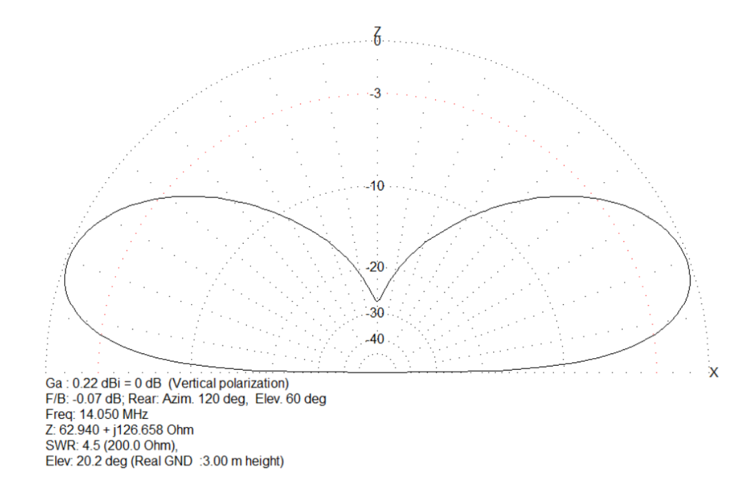 MMANA Antenna Model (20 Meter Band)This model shows that the antenna presents a uniform low-angle radiation pattern at the 20-meter band.
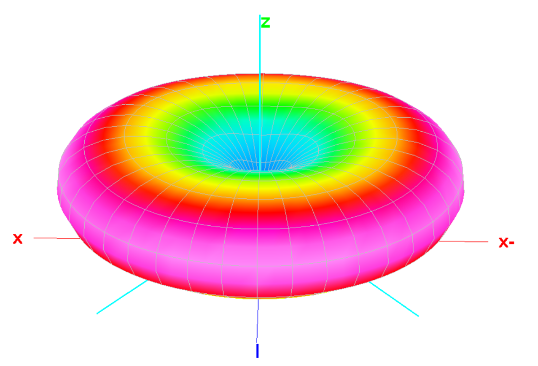 MMANA 3D Antenna Model (20 Meter Band)This 3D model shows that the antenna presents a uniform low-angle radiation pattern at the 20-meter band.
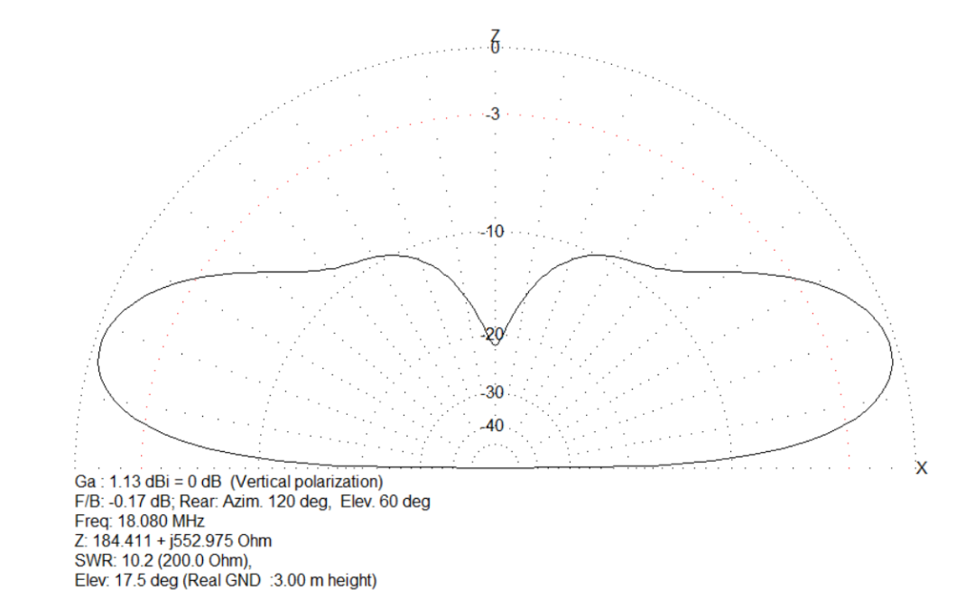 MMANA Antenna Model (17 Meter Band)This model shows that the antenna presents a uniform low-angle radiation pattern at the 17-meter band.
 MMANA 3D Antenna Model (17 Meter Band)This 3D model shows that the antenna presents a uniform low-angle radiation pattern at the 17-meter band.
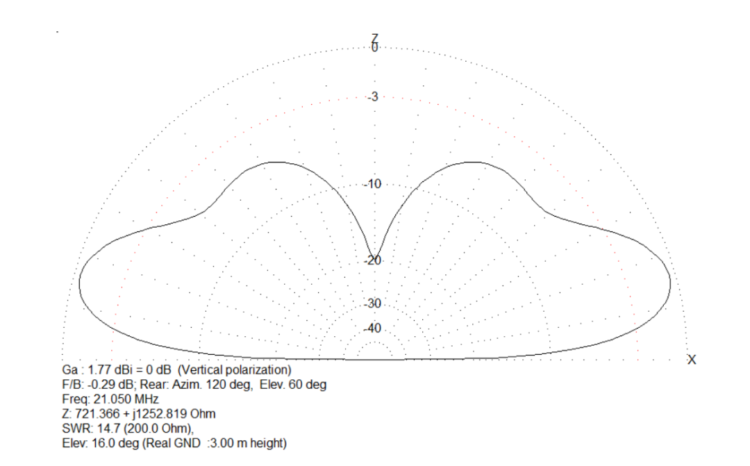
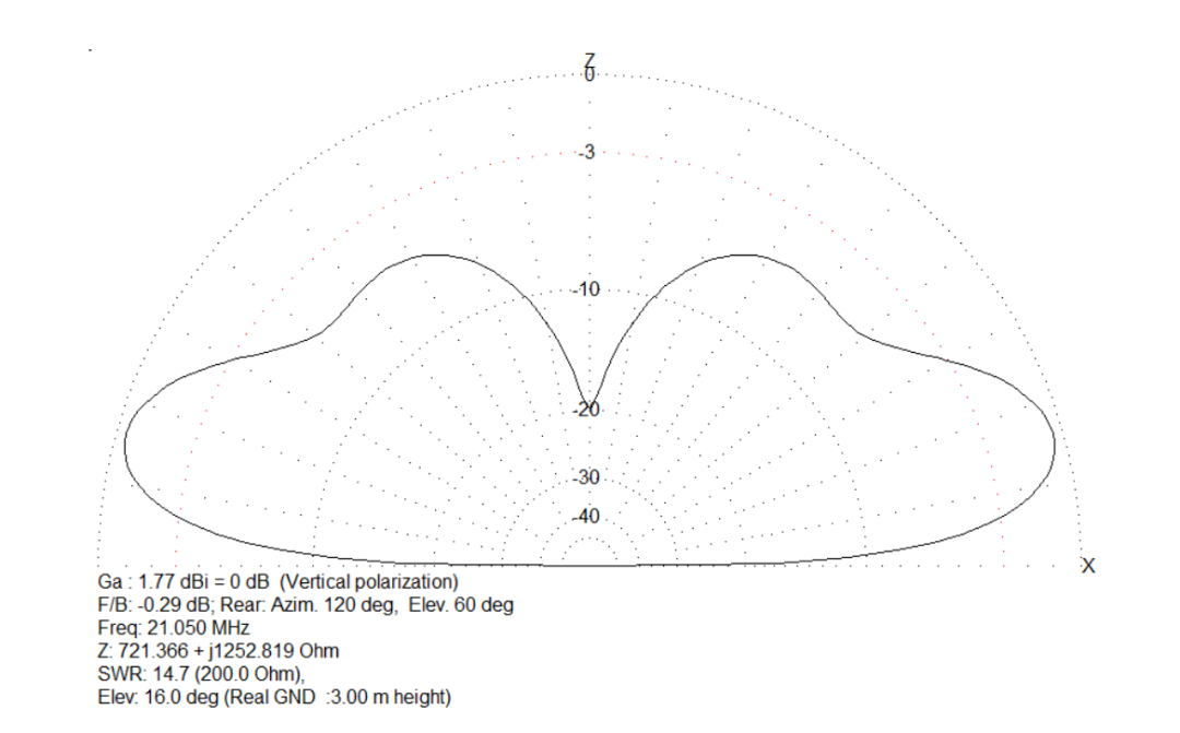 MMANA Antenna Model (15 Meter Band)This model shows that the antenna presents a uniform low-angle radiation pattern at the 15-meter band.
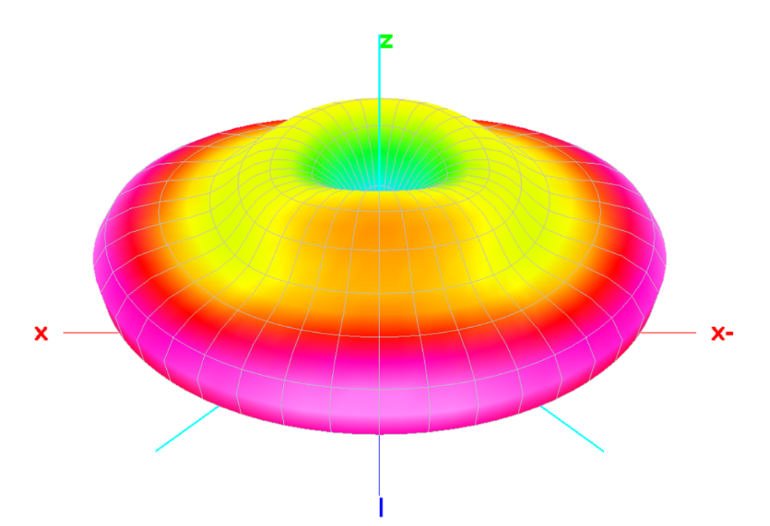 MMANA 3D Antenna Model (15 Meter Band)This 3D model shows that the antenna presents a uniform low-angle radiation pattern at the 15-meter band.
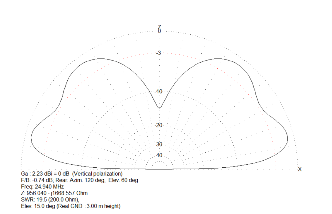 MMANA Antenna Model (12 Meter Band)This model shows that the antenna presents a uniform low-angle radiation pattern at the 12-meter band.
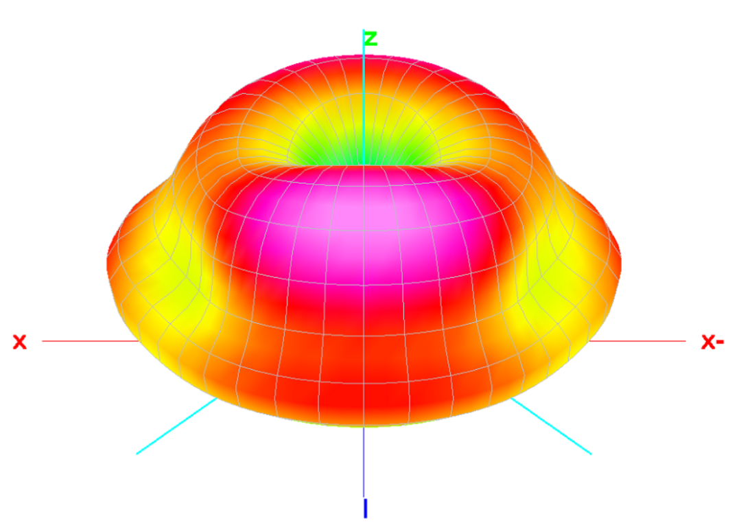 MMANA 3D Antenna Model (12 Meter Band)This 3D model shows that the antenna presents a uniform low-angle radiation pattern at the 12-meter band.
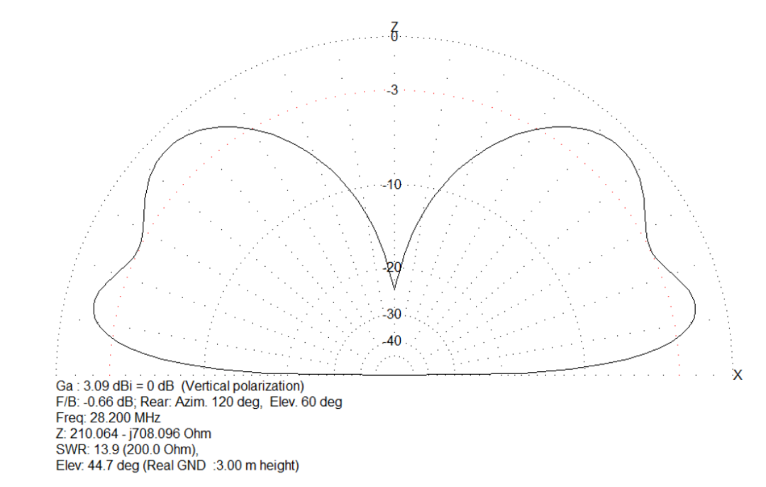 Figure 6: MMANA Antenna Model (10 Meter Band)This model shows that the antenna still presents a uniform low-angle radiation pattern at the 10-meter band, but a high-angle radiation peak has appeared.
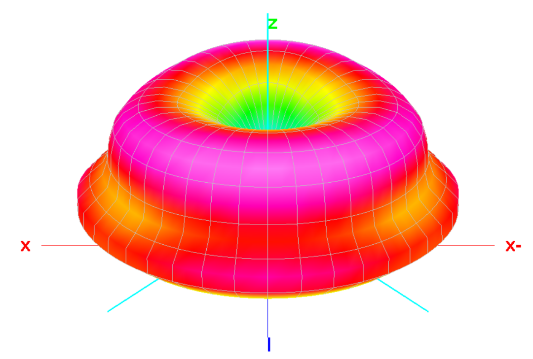 Figure 6: MMANA 3D Antenna Model (10 Meter Band)This 3D model shows that the antenna still presents a uniform low-angle radiation pattern at the 10-meter band, but a high-angle radiation peak has appeared.05Key Terminology Explanation
- Radial Element: Translated as “radial element”, refers to the wire or metal structure extending outward from the feed point in a ground plane antenna, used to simulate an ideal ground and enhance antenna performance.
- Balun: Full name “Balance-Unbalance Transformer”, translated as “balun”, serves to connect balanced loads (such as antennas) to unbalanced transmission lines (such as coaxial cables), suppressing common mode currents and matching impedance.
- Squid Pole: A multi-section telescopic lightweight antenna support pole, named for its resemblance to squid tentacles when extended, translated as “squid pole”, commonly used for field setup of portable antennas.
- NanoVNA: A “vector network analyzer”, a compact, low-cost RF testing instrument used to measure antenna impedance, SWR, and other parameters.
- MMANA-GAL: A professional antenna simulation software commonly used to predict and analyze antenna radiation patterns, impedance characteristics, and other performance parameters, providing references for antenna design and optimization.