
📌 Reading Notes
🕒 This article has 3125 words, approximately 5 minutes reading time
💡 The content is concise, but some effort was put into organizing it
💬 If you have any questions, feel free to leave a comment for discussion
👍 If you find it useful, remember to like/recommend to support!
💗 Your likes and recommendations are my motivation to keep updating!
Experiment Simulator
The simulator uses H3C’s HCL, and this experiment is supported by H3C’s HCL simulator.
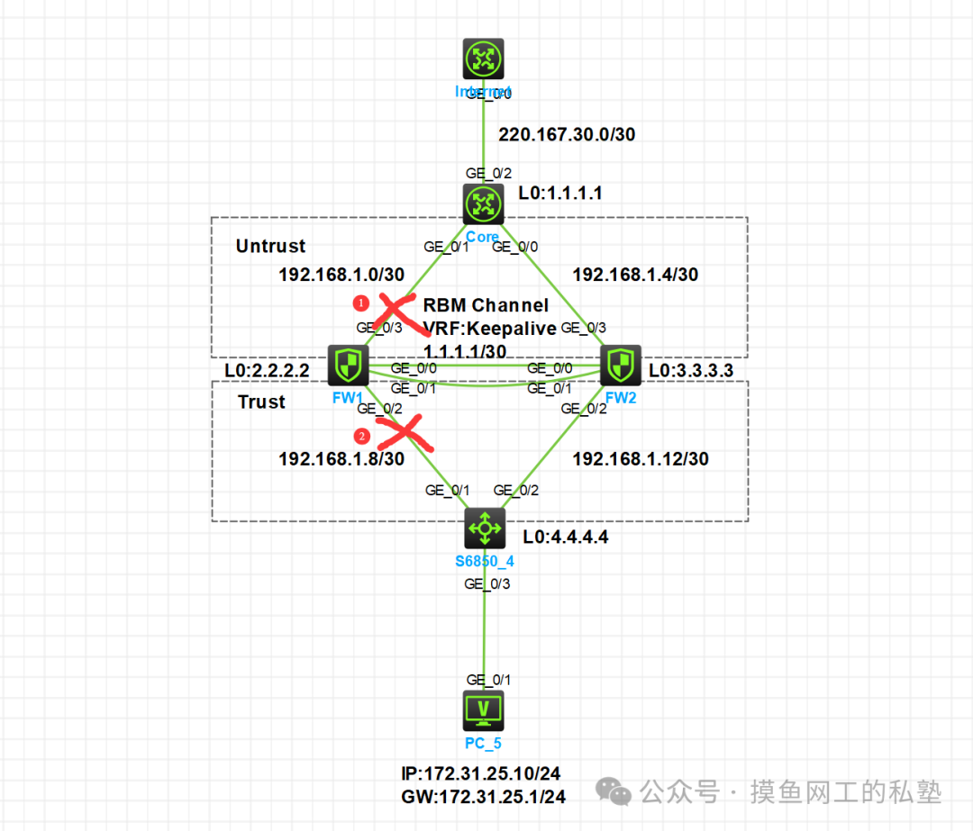
Experiment Topology
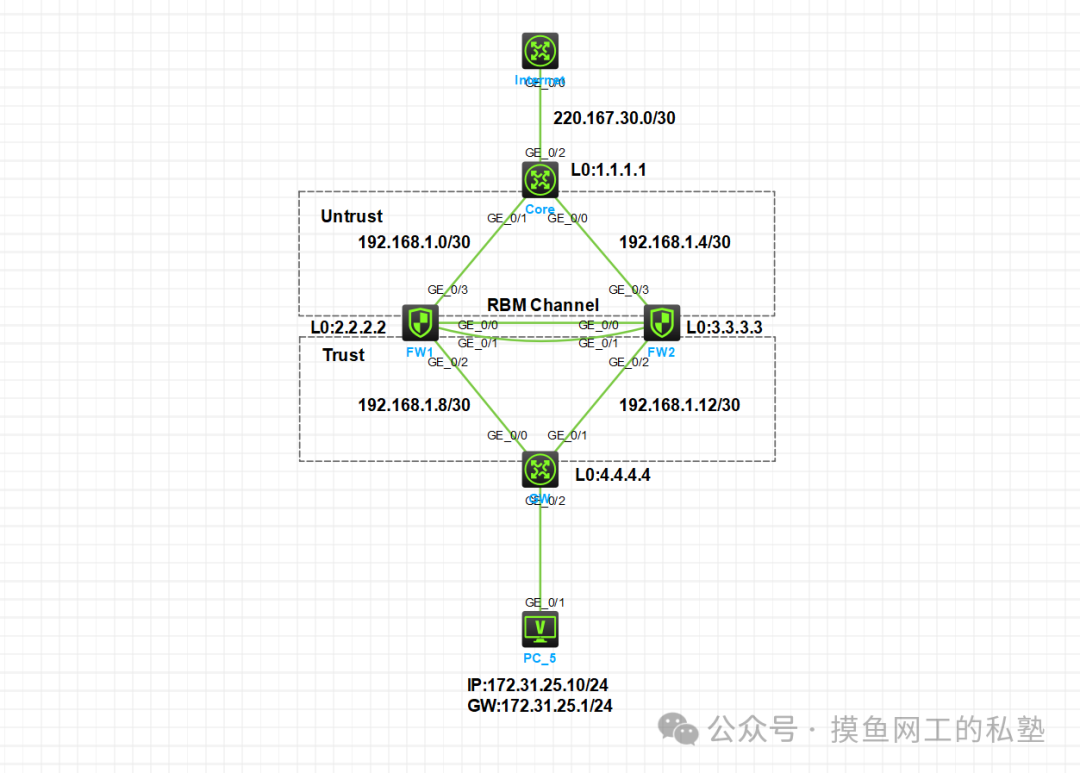
The technologies used in this session include: <span>OSPF</span>, <span>RBM</span>, <span>NAT</span>, <span>Security Policies & Service Objects</span>, <span>VRF</span>
Experiment Planning Requirements
- Configure the IP addresses of each device according to the topology, using a /30 subnet mask for interconnecting interface addresses.
- Configure OSPF to connect the entire network, noting that OSPF policies must be allowed in the corresponding security domains on the firewall; otherwise, hello packets cannot be transmitted.
- The firewall will add the corresponding interfaces to the respective security domains and set policies to allow Ping.
- Configure RBM on the firewall after completing the configuration of all critical business data, and configure according to the sequence of Master and Backup.
Experiment Steps
The interconnecting addresses between devices are omitted. Note that the Core needs to configure a default route pointing to the Internet to simulate external network access. Configure EasyIP on the Core’s outgoing interface to simulate connection to the carrier’s network.
1. Configure OSPF to Connect the Entire Network
Use the L0 address as the OSPF router-id.
Core Configuration
[Core]ospf router-id 1.1.1.1
[Core-ospf-1]area 0
[Core-ospf-1-area-0.0.0.0]net 192.168.1.0 0.0.0.3
[Core-ospf-1-area-0.0.0.0]net 192.168.1.4 0.0.0.3
[Core-ospf-1]default-route-advertise
[Core-ospf-1]import-route static
FW1 Configuration
[FW1]ospf router-id 2.2.2.2
[FW1-ospf-1]area 0
[FW1-ospf-1-area-0.0.0.0]net 192.168.1.0 0.0.0.3
[FW1-ospf-1-area-0.0.0.0]net 192.168.1.8 0.0.0.3
FW2 Configuration
[FW2]ospf router-id 3.3.3.3
[FW2-ospf-1]area 0
[FW2-ospf-1-area-0.0.0.0]net 192.168.1.4 0.0.0.3
[FW2-ospf-1-area-0.0.0.0]net 192.168.1.12 0.0.0.3
GW Configuration
[GW]ospf router-id 4.4.4.4
[GW-ospf-1]area 0
[GW-ospf-1-area-0.0.0.0]net 192.168.1.8 0.0.0.3
[GW-ospf-1-area-0.0.0.0]net 192.168.1.12 0.0.0.3
[GW-ospf-1-area-0.0.0.0]net 172.31.25.0 0.0.0.255
FW1 and FW2 Configure Interfaces to Join Security Domains and Set OSPF, Ping Allow Policies
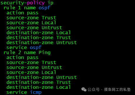

FW1 Configuration:
/* Enter Untrust Security Domain */
[FW1]security-zone name Untrust
/* Import physical interface into Untrust Security Domain */
[FW1-security-zone-Untrust]import interface g1/0/3
/* Enter Trust Security Domain */
[FW1]security-zone name Trust
/* Import physical interface into Trust Security Domain */
[FW1-security-zone-Trust]import interface g1/0/2
/* Enter IPv4 Security Policy */
[FW1]security-policy ip
/* Create rule with ID 1, named ospf */
[FW1-security-policy-ip]rule 1 name ospf
/* Source security domain is Trust */
[FW1-security-policy-ip-1-ospf]source-zone Trust
/* Destination security domain is Local */
[FW1-security-policy-ip-1-ospf]destination-zone Local
/* Source security domain is Local */
[FW1-security-policy-ip-1-ospf]source-zone Local
/* Destination security domain is Trust */
[FW1-security-policy-ip-1-ospf]destination-zone Trust
/* Source security domain is Untrust */
[FW1-security-policy-ip-1-ospf]source-zone Untrust
/* Destination security domain is Untrust */
[FW1-security-policy-ip-1-ospf]destination-zone Untrust
/* Service type is ospf */
[FW1-security-policy-ip-1-ospf]service ospf
/* The action of this policy is to allow */
[FW1-security-policy-ip-1-ospf]action pass
/* Create object service group, named icmp */
[FW1]object-group service icmp
/* Bind service icmp in the service group */
[FW1-obj-grp-service-icmp]service icmp
/* Enter IPv4 Security Policy */
[FW1]security-policy ip
/* Add rule 2 named Ping */
[FW1-security-policy-ip]rule 2 name Ping
[FW1-security-policy-ip-2-Ping]source-zone Trust
[FW1-security-policy-ip-2-Ping]source-zone Untrust
[FW1-security-policy-ip-2-Ping]destination-zone Untrust
[FW1-security-policy-ip-2-Ping]destination-zone Trust
/* Service type is the previously created service object group ping */
[FW1-security-policy-ip-2-Ping]service icmp
/* The action of this policy is to allow */
[FW1-security-policy-ip-2-Ping]action pass
FW2 Configuration:
[FW2]security-zone name Untrust
[FW2-security-zone-Untrust]import interface g1/0/3
[FW2]security-zone name Trust
[FW2-security-zone-Trust]import interface g1/0/2
[FW2]security-policy ip
[FW2-security-policy-ip]rule 1 name ospf
[FW2-security-policy-ip-1-ospf]source-zone Trust
[FW2-security-policy-ip-1-ospf]destination-zone Local
[FW2-security-policy-ip-1-ospf]source-zone Local
[FW2-security-policy-ip-1-ospf]destination-zone Trust
[FW2-security-policy-ip-1-ospf]source-zone Untrust
[FW2-security-policy-ip-1-ospf]destination-zone Untrust
[FW2-security-policy-ip-1-ospf]service ospf
[FW2-security-policy-ip-1-ospf]action pass
[FW2]object-group service icmp
[FW2-obj-grp-service-icmp]service icmp
[FW2]security-policy ip
[FW2-security-policy-ip]rule 2 name Ping
[FW2-security-policy-ip-2-Ping]source-zone Trust
[FW2-security-policy-ip-2-Ping]source-zone Untrust
[FW2-security-policy-ip-2-Ping]destination-zone Untrust
[FW2-security-policy-ip-2-Ping]destination-zone Trust
[FW2-security-policy-ip-2-Ping]service icmp
[FW2-security-policy-ip-2-Ping]action pass
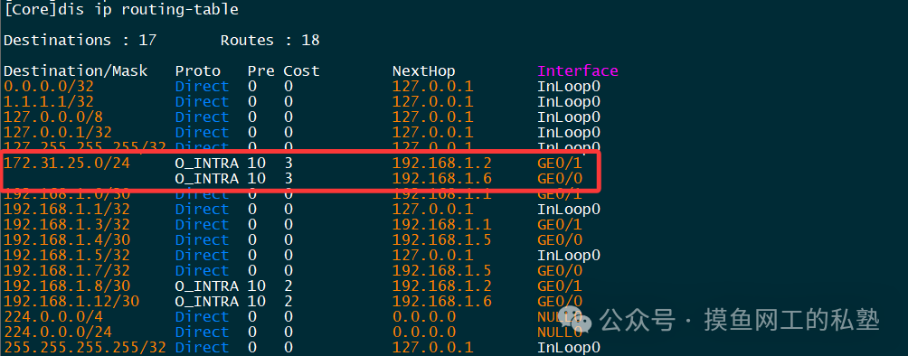
[1] Check if the OSPF neighbor status on Core is normal and if it has learned the internal business routes.
By executing the command <span>display ospf peer</span> on the Core router, check the OSPF neighbor status.

By executing the command <span>display ip routing-table</span> on the Core router, check the routing table.
[2] Network Connectivity Ping Test
Ping the business address from Core to check connectivity. Note that during testing, the interface of the second firewall needs to be shut down. The Core router learns the business routes through both FW1 and FW2, and the business route on the Core will be load-balanced. When sending packets downstream, since the current firewalls have not formed a dual-active state, the firewall will check the packet’s five-tuple, and inconsistent return paths will cause blocking. Therefore, the interface of one firewall needs to be shut down for testing.

Configure Firewall Dual-Active RBM
FW1 Configuration
The general configuration process is as follows:
- Configure data and control channel aggregation and set IP addresses.
- Set the device backup mode to dual-active.
- Configure device roles.
- Enable automatic data backup functionality.
- Enable hot backup business table entry functionality.
- Enable traffic failback functionality.
- Configure data channels.
- Configure control channels.
/* Create Layer 3 aggregation interface and add the corresponding physical interfaces of the two firewalls to the aggregation group (omitted) */
[FW1]interface Route-Aggregation 10
/* Change aggregation mode to dynamic, bind VRF and configure IP address */
[FW1-Route-Aggregation10]link-aggregation mode dynamic
[FW1-Route-Aggregation10]ip binding vpn-instance keepalive
[FW1-Route-Aggregation10]ip address 1.1.1.1 30
/* Enter RBM for configuration */
[FW1]remote-backup group
/* Set backup mode to dual-active */
[FW1-remote-backup-group]backup-mode dual-active
/* Configure device role as primary */
[FW1-remote-backup-group]device-role primary
/* Enable automatic data backup functionality */
RBM_P[FW1-remote-backup-group]running-data auto-sync enable
/* Enable business table entry backup functionality */
RBM_P[FW1-remote-backup-group]hot-backup enable
/* Enable configuration consistency check functionality */
RBM_P[FW1-remote-backup-group]configuration auto-sync enable
/* Configure traffic failback functionality */
RBM_P[FW1-remote-backup-group]delay-time 1
/* Configure data channel */
RBM_P[FW1-remote-backup-group]data-channel interface Route-Aggregation 10
/* Configure control channel local end-to-end source and destination IP */
RBM_P[FW1-remote-backup-group]local-ip 1.1.1.1
RBM_P[FW1-remote-backup-group]remote-ip 1.1.1.2
After configuration, both FW1 and FW2 should be in an Active state.
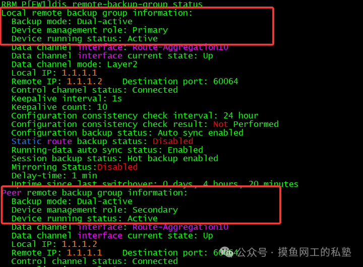
It can be seen that both the local and remote ends are in an Active state, with the control layer being the primary.
Core Outbound Configuration Easy NAT
Prior to this, the Core’s main configuration was for the interface connecting to the Internet. If you need reference configurations, please obtain them at the bottom of the article. Configure EasyNAT to enable internal network access to the external network.
/* Create basic ACL to capture internal network traffic */
[Core]acl basic 2000
/* Match 172.31.25.0/24 */
[Core-acl-ipv4-basic-2000]rule 0 permit source 172.31.25.0 0.0.0.255
/* Enter the interface connecting to the Internet */
[Core]interface GigabitEthernet0/2
/* Apply NAT in Outbound to complete EasyNAT configuration */
[Core-GigabitEthernet0/2]nat outbound 2000
After configuration, verify if the PC can access the Internet.

Failover Testing
Test whether there is packet loss when the firewall link fails.
Ping the external network from the PC to check for packet loss.


No packet loss was found, so further check the port FW to GW link.

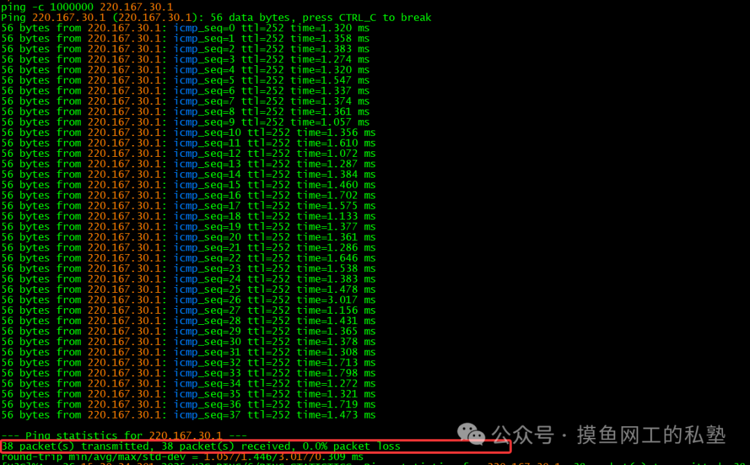
Again, no packet loss was found, and FW2 is currently handling traffic forwarding. This concludes our content for this session.
Summary
Follow the public account to obtain project files, and reply with the keyword <span>Firewall Dual-Active Direct Route Deployment Case</span> to obtain detailed project files, configuration information, etc. If you find this article helpful, feel free to share it with friends who need it! If there are any shortcomings in the writing, please feel free to point them out~ See you in the next article!

Previous Content:
Real-World Case: Firewall Side-Hanging Deployment Scheme in M-LAG Scenario [2] Firewall Configuration PartReal-World Case: Firewall Side-Hanging Deployment Scheme in M-LAG Scenario [1]QinQ Technology Explained: From VLAN Expansion to Carrier Network ApplicationsThe Secrets Behind Campus Networks/Hotel Wi-Fi: Full Process of Portal Authentication RevealedPort-Based Network Access Control: 802.1X Principles and Practices