In the previous article, we discussed that there are eight control buttons, but the number of I/O ports on the microcontroller is insufficient. One button called PIN_ESC is connected to D8, which is pin 15, but it is actually non-functional. Pin 15 is pulled down to ground through a 10k resistor. This button is the B button, which is very important, so adjustments were made to some interfaces:
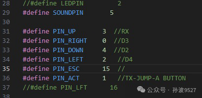
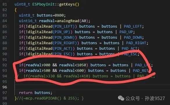
In the lib folder, the ESPBoyInit.h👆 file was rewritten in the corresponding ESPBoyInit.cpp
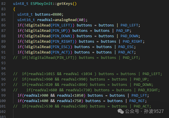
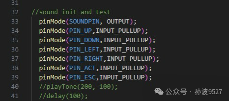
The specific functions of each button and their corresponding development board numbers are commented, and they can be connected one by one. The connection method for the LCD pins remains unchanged.
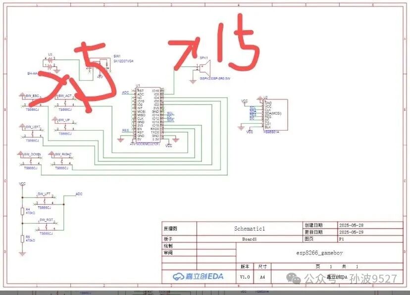
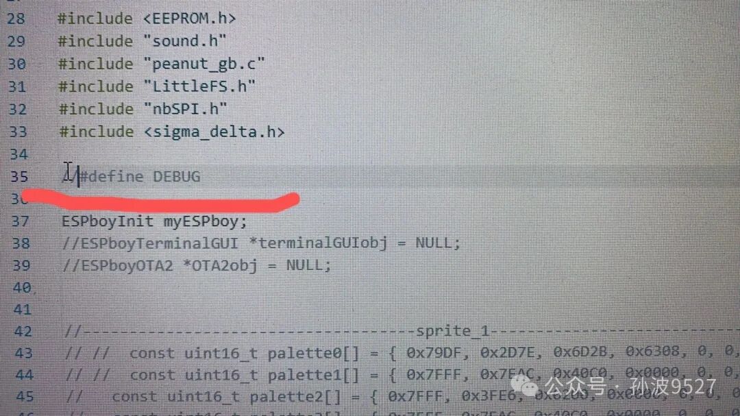
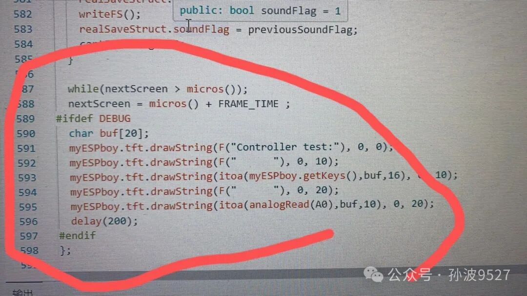
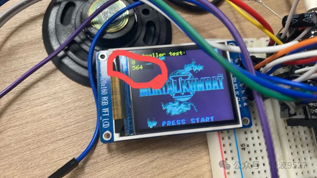
We swapped the positions of the speaker interface and PIN_ESC. However, this will first require the speaker connection to be as shown in the diagram above with a pull-down configuration; a pull-up will cause the microcontroller to stop working. Secondly, the sound from the speaker becomes quieter because the 10k resistor acts as a shunt. I used an 8-ohm 5W speaker; I don’t understand impedance matching, so I just picked one randomly. You can also add an amplifier stage for matching, but under such a sampling rate, adding an output capacitor will suffice; it all sounds like a cacophony. Finally, although we are using a color screen, the Game Boy is actually a monochrome console; we only used the size of the color screen, and the colors are black and white, with the LCD green being the most visually pleasing. I replaced the resistors for the two buttons on the A0 interface with 10k ones. I set a DEBUG define in the ino file, which can be uncommented to view the actual ADC readings of the buttons for threshold adjustments.