PROFIBUS Wiring
 Please refer to the document: Profibus Wiring
PROFIBUS Connectors and Termination Resistors
The connector is used to connect the ROFIBUS cable to the PROFIBUS stations (as shown in Figure 1).
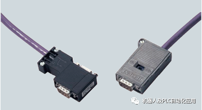
Figure 1 Usage of PROFIBUS Connector
On the PROFIBUS connector, there is an incoming port (In) and an outgoing port (Out), which connect to the previous and next stations, respectively.
1. For each physical network segment, the connectors on the two terminal stations need to connect the network cable to the incoming port “In” and set the termination resistor to “On” (as shown in Figure 2).
2. For stations located in the middle of the network segment, the network cable should be connected sequentially to the incoming port “In” and the outgoing port “Out”, while setting the termination resistor (as shown in Figure 2).
3. For easier system diagnostics and maintenance, it is recommended to use connectors with programming ports at least at the two terminal stations of each network segment (as in the left connector in Figure 1).


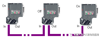
Figure2 PROFIBUS Connector Connection and Settings
4. For terminal devices in the bus that are connected via wiring (non-PROFIBUS connectors), use the self-connected termination resistors as shown in Figure 6, or use the active termination resistors from item 6.
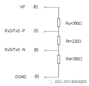
Figure 3 Composition of Termination Resistors
5. When the device at the terminal position drops out or is turned off manually, the resistor on the standard connector will also become ineffective. Therefore, the overall network will lack the termination resistor at this terminal, which may lead to a failure of the entire network.
Siemens provides active termination resistors (6ES7 972-0DA00-0AA0) to ensure that the resistor at this terminal position remains effective.

Figure 4 Active Termination Resistor
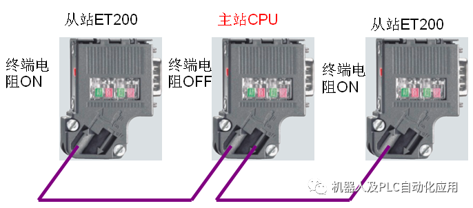
 Can the CPU be placed in the middle of the bus network?
Yes. As shown in the figure, note that when the CPU is placed in the middle, the termination resistors should be set to OFF.
If the PROFIBUS cable is broken or not long enough, can it be extended?
Yes, it can be extended. You need to connect the two cables together, but do not simply twist the two copper cores together, as this will damage the characteristic impedance of the cable and will lead to communication issues.
1. You can use a pair of connectors as shown in the figure below to connect the two cables that need to be joined.

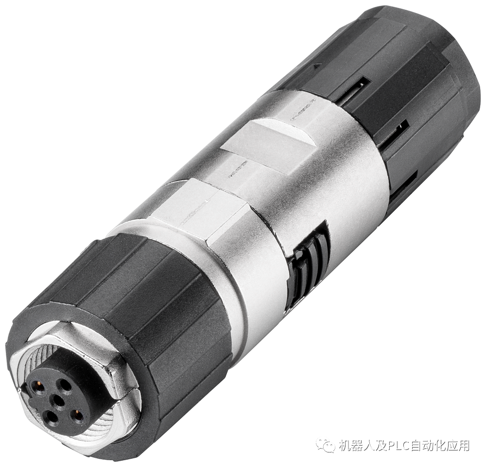
Order numbers: 6GK1905-0EA10 and 6GK1905-0EB10
2. A repeater can also be used for connection.
PROFIBUS Installation Specifications
Here are the precautions for PROFIBUS installation, along with some on-site examples for illustration.
Precautions:
 Each network can theoretically connect a maximum of 127 physical stations, including master stations, slave stations, and repeater devices;
Each segment supports 32 physical devices (nodes); if this number is exceeded, a 485 repeater needs to be added, with a maximum of 9 repeaters allowed in each network.
For wiring and usage of the 485 repeater, please refer to: Introduction to 485 Repeaters
The network supports multiple master stations, but it is not recommended to have more than 3 master stations in the same network;
Generally, 0 is the PG address, 1-2 are master station addresses, 126 is the default address for some slave stations, and 127 is the broadcast address; therefore, these addresses are generally not assigned to slave stations, so up to 124 DP slave stations can be connected, with station numbers typically set to 3-125.
Network Wiring Rules
Select Standard PROFIBUS Communication Cable
The characteristic impedance of standard PROFIBUS communication cable is 150 ohms, which matches the termination resistor value when the PB head’s termination resistor is set to “ON”. If ordinary cables are chosen, their characteristic impedance may not match the termination resistor, which will affect communication performance.
Standard PROFIBUS cables are often double-shielded, providing good shielding effectiveness. Additionally, standard communication cables are twisted pairs, which help self-suppress interference generated during signal transmission within the cable.
Multi-point Grounding of Shielding Layers
When wiring the PROFIBUS cable at the connector, the shielding layer must be stripped and pressed against the metal part inside the connector, which is connected to the external metal part of the Sub-D connector. When the connector is plugged into the DP port of devices like CPU or ET200M, it connects through the device to the mounting backplane, which is generally grounded.

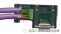
Figure 5 Internal Wiring of PROFIBUS Connector and Shielding Layer Treatment
Since grounding is beneficial for protecting PLC devices and DP communication ports, all PROFIBUS stations are required to have grounding treatment, referred to as “multi-point grounding”.
Wiring Rules (Important)
a. Cables of different voltage levels should be wired in separate troughs.
High voltage, high current power cables should be wired separately from low voltage and low current cables, and the trough should be covered with a lid to be as fully enclosed as possible. If separate trough wiring is not possible on-site, the two types of cables should be kept as far apart as possible, with a metal partition in between for isolation, and the metal trough should be grounded (Figure 6).
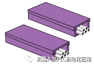
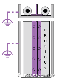
Figure 8 Cable Trays and Treatment of Cables in Trays


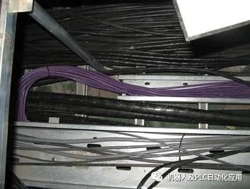
Figure 7 On-site Wiring
The connection between cable trays should also ensure that metal connecting parts are connected over a large area, while paying attention to the connection for “grounding”.
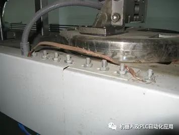
Figure 8 Connection and Grounding Treatment Between Cable Trays
b. When wiring communication cables outside the trough, the use of metal pipes may be adopted based on the situation. This can protect communication cables from damage and help prevent EMC interference, but note that the external metal pipe needs to be grounded.
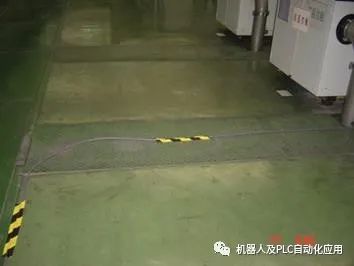
Figure 9 On-site Communication Cables
The cables in Figure 9 are directly exposed, making them prone to being crushed. In similar situations, consider using partial or full piping.
c. Avoid long-distance parallel wiring between communication cables and power cables.
Due to the need to consider spatial capacitive coupling between two cables wired in parallel, to avoid mutual interference, parallel wiring should be avoided (Figure 10).
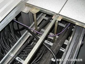
Figure 10 Communication Cables Running Parallel to Power Cables in Trays
In Figure 10, the communication cables not only do not meet principles a. or b., but instead run parallel to larger power cables, which can make them more susceptible to interference from the power cables.
Cables can be crossed:
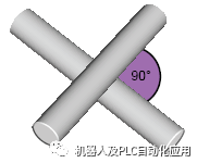
Two crossed cables will not interfere with each other due to capacitive coupling.
d. Try to keep cables close to large metal plates (Figure 11).
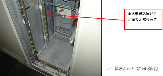 |
Figure 11 Communication Cables Close to Metal Plates
Communication cables should be kept close to large metal plates or “ground planes”.
e. When communication cables are too long, do not form loops (Figure 12).
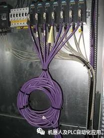
Figure 12 Communication Cable Forming a Loop
If magnetic field lines pass through the center of the loop, according to the “right-hand rule”, interference signals can easily be generated.
In Figure 12, although the backplane is a large metal plate, since the project has been completed, there is no possibility of changing the cable length. Therefore, it is still recommended that users cut the excessively long cables and place them in the cable tray inside the cabinet.
f. Devices connected to communication lines should be connected to the same potential.
PROFIBUS connected stations may be widely distributed. To ensure communication quality, it is generally required that all communication stations should be at the same voltage level, i.e., they should all be “at the same potential” (Figure 13).
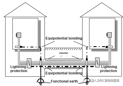
Figure 13 Communication Stations Should Be Treated as “At the Same Potential”
If there is a potential difference between the “ground” of two stations, when both devices are grounded separately, a potential difference will occur between the two grounding points, causing current to flow through the shielding layer of the communication cable, thus affecting communication. Therefore, an equipotential bonding should be performed between the two devices.
Equipotential lines can be used to connect the “ground” of the two devices, with specifications for equipotential lines: copper 6mm2, aluminum 16mm2, steel 50mm2.
Of course, this does not mean that all sites need to add additional equipotential lines to increase costs; it is only recommended that if there are situations of unequal grounding potential that affect communication or may cause equipment damage, improvements should be made.
If communication instability is caused by grounding points, such as if a certain system’s “ground” has strong interference, grounding the shielding layer here may adversely affect PROFIBUS communication. Therefore, it is recommended to first address the “ground” issue before grounding the PROFIBUS shielding layer.
Providing a good “ground” for on-site equipment and ensuring proper “grounding” is a prerequisite for improving EMC characteristics (Figure 14).
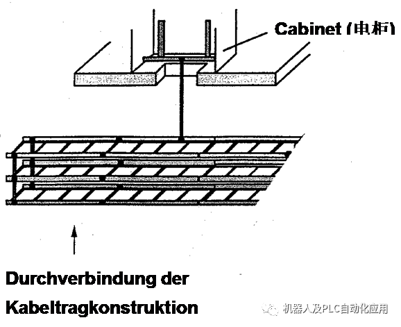
Figure 14 Good Ground Design and Implementation for the System
g. Wiring of communication lines inside the electrical cabinet.
When wiring communication cables within the electrical cabinet, the previous principles should also be followed, keeping them away from sources of interference.
Routing inside the cabinet should be carefully designed to avoid running alongside high voltage and high current cables in the same trough (Figure 15), and avoid forming loops inside the cabinet, especially avoiding surrounding interference sources such as inverters within a loop.

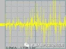
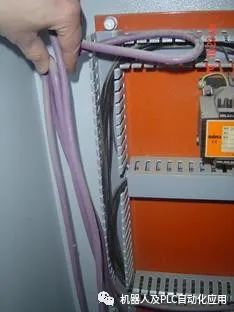
Figure 15 Interference Situations of Communication Cables and Power Cables Inside the Cabinet
Treatment of Communication Cable Shielding Layer Inside the Cabinet
First, for the PROFIBUS connector, in addition to the previous instructions to press the shielding layer against the metal part of the connector, it is also important to ensure that the shielding layer is not stripped too long, otherwise it will be exposed in space and become an easily interfered “antenna” (Figure 16).

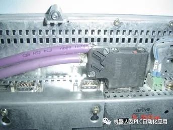
Figure 16 Shielding Layer Exposed in Space Easily Receives Interference
The shielding layer of communication cables should be grounded when entering/exiting the electrical cabinet.
The shielding layer should ensure large-area contact with the grounding copper bar (Figure 17).
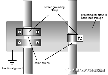
Figure 17 Grounding of Shielding Layer
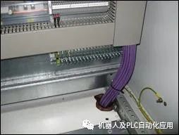
The shielding layer of communication cables should be grounded when entering/exiting the electrical cabinet. This prevents external interference signals from entering the cabinet and avoids interference generated inside the cabinet from affecting external devices (Figure 18).
 |
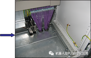 |
Figure 18 Grounding Treatment of Shielding Layer Inside the Cabinet
If communication cables need to be connected through terminals inside the cabinet, the shielding layer should preferably be connected on both sides of the terminal block (Figure 19).
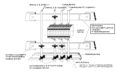
Figure 19 Shielding Layer Treatment When Communication Cables Connect Through Terminals
A practice to avoid is stripping the shielding layer and twisting it into one connection to the terminal (Figure 20). This practice is known in the EMC field as the “pig tail” effect.
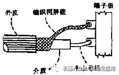
Figure 20 “Pig Tail Effect” at Shielded Cable Connection Point
In on-site connections, if the shielding layer is stripped too long, the communication cable will have a long section without the shielding layer “protection”, and twisting the shielding layer into one will form an antenna, making it easier to introduce interference into the system (Figure 21).
|

|
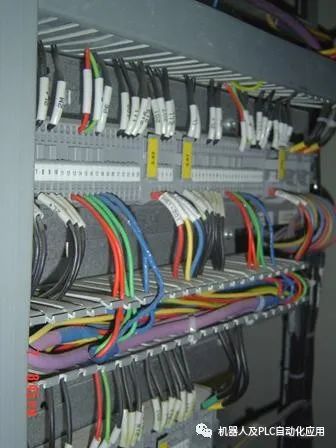
Figure 21 Connection of Shielded Cable “Pig Tail”
Overvoltage Protection
If there is a risk of overvoltage in the application, please use direct-buried cables outside the cabinet, and install overvoltage protection devices on the cables inside and outside the cabinet (Figure 40).
If there is a risk of lightning, please refer to lightning protection design standards for lightning protection design.
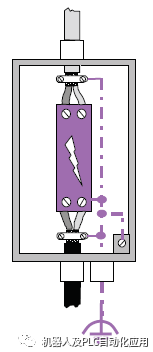
Figure 22 Overvoltage Protection Device
Reducing the Impact of Interference Sources such as Inverters on Communication
Devices with large power, such as inverters, can interfere with normal operation through power interference and spatial radiation interference. As these devices now have the capability for PROFIBUS communication, the interference they generate may also directly enter the communication system, so EMC processing for inverters should be performed.
First is the installation of the inverter. In the electrical cabinet, try to use a galvanized base plate instead of a painted base plate as the mounting backplate (Figure 23) to improve EMC characteristics.
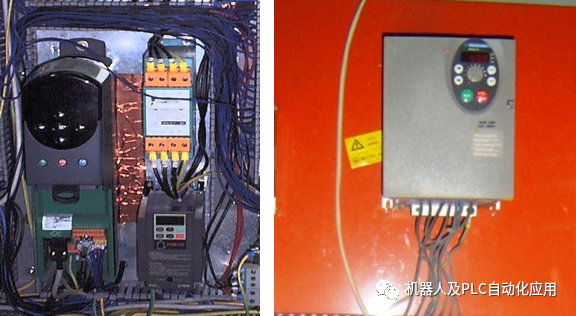
Figure 23 Using Galvanized Base Plate Instead of Painted Base Plate
The output lines of the inverter should also undergo corresponding EMC treatment, such as using shielded communication cables with grounding, or using ferrite magnetic rings for filtering (Figure 24).
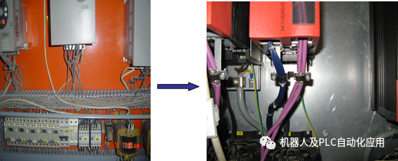
Figure 24 Standard EMC Treatment for Inverter Cables