 Today we continue to explain the subsequent content of DRBG.——- DRBG nonce V (i.e., VDRBG)
As described in Section 3.1.5, the instantiation of the random number V vector represents the initial value of the DRBG increment function. From this initial value, multiple random number counter fields are defined, as shown in Table 3.3. Each counter field byte is arranged in bit format from left to right, from bit 7 to bit 0.
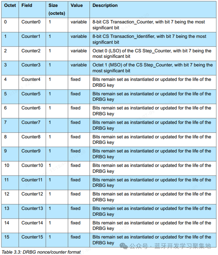
It is important to focus on the four fields counter0-counter4, which are variable and need to be changed differently based on different scenarios to ensure sufficient randomness.
——- DRBG nonce increment function
The link layer should maintain a DRBG random number/counter (V) value for each ACL connection, as described in Section 3.1.5. This section describes how to manage the CS step counter field, CS transaction identifier field, and CS transaction counter field of the random number V. All other fields in the random number V counter should be set relative to the VDRBG content generated by the process described in Section 3.1.5 or the anti-backtracking process described in Section 3.1.7.
The CS step counter field of the random number V should be initialized from the VDRBG value generated by the instantiation process in Section 3.1.5 or the anti-backtracking process in Section 3.1.7. This value will be used for the DRBG call required at the start of the first step of the CS process. After that, as described in [Vol 6] Part H Section 4.3, when DRBG is called again, the initial value of the CS step counter of the random number V should be added to the step number CSStepCount, modulo 2^16.

In each instance of the CS process, when the CS step counter value is used for the CS step counter field of the random number V, its value must not exceed 2^16-1. DRBG will not be called at every step of the CS process.
The CS transaction identifier field of the random number V should be set to a specific transaction label CSTransactionID (definition found in [Vol 6] Part H Section 4.8), plus the VDRBG value generated by the instantiation process (see Section 3.1.5) or the anti-backtracking process (see Section 3.1.7), modulo 2^8.

The CS transaction counter field of the random number V will increment with each type of CS transaction identifier defined in [Vol 6] Part H Section 4.8. That is, for each type of CS transaction identifier, DRBG may need to be called once or multiple times.
Whenever DRBG is called for a specific CS transaction identifier type at a specific CS step, the CS transaction counter field should increment. A separate CS transaction counter field value must be maintained for each possible CS transaction identifier type, as the calls to DRBG at any CS step may interleave with different CS transaction identifier types. In the next two paragraphs, all possible CS transaction counter field values are collectively referred to as the CS transaction counter field.
Each time the CS step counter field of the random number V is set to a new value, the CS transaction counter field should be initialized to the VDRBG value generated by the instantiation process (see Section 3.1.5) or the anti-backtracking process (see Section 3.1.7). Before each DRBG call, for a specific CS transaction identifier field setting, the initial value of the CS transaction counter should be added to the transaction counter CSTransactionCounter defined in [Vol 6] Part H Section 4.8.For any single combination setting of the CS transaction identifier field and the CS step counter field, the number of increments of the CS transaction counter field must not exceed 2^8-1.

——- CS Random Bit Generation
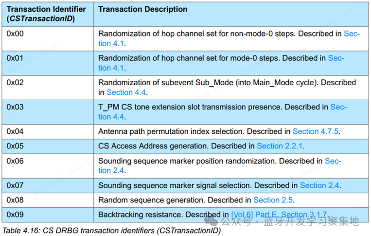
The dedicated channel probing Deterministic Random Bit Generator (CS DRBG) is used to coordinate the randomization of various transaction types in the CS process. These transaction types are identified by the value of the transaction identifier type, as shown in Table 4.16. CSTransactionID represents the transaction identifier processed by the CS DRBG. The toolbox function CS_DRBG used for random bit generation is described in Section 3.1.6 of [Vol 6]E.The CSTransactionID mentioned above is used to update the VDRBG field.
Each transaction listed in Table 4.16 uses a new set of random bits at different stages of the CS process. Each transaction may use a different number of random bits, which may be less than the 128-bit output generated by the CS DRBG. If not all bits are used in a transaction, the remaining bits should be retained for subsequent transactions until there are not enough remaining bits to complete the transaction. At that point, the remaining bits should be discarded, and a new set of 128-bit random bits should be generated.
In each CS step, it may not be necessary to generate a new set of random bits for the following reasons: 1) For that specific transaction identifier, there are still enough unused bits remaining from previous DRBG calls; 2) The specific CS mode of that CS step does not require the use of random bits.
For example, if a transaction identifier uses random bits in units of 8 bits at each step, then at step 0, DRBG will be called to provide 128 bits of random bit output. The first 8 bits will be used in step 0, and the remaining 120 bits will be used in subsequent steps 1 to 15 in units of 8 bits. At step 16, since there are not enough bits to complete that step, a new set of 128-bit random bits will be generated, and the bit allocation process will be repeated. When generating a new set of 128-bit random bits, the CS Step_Counter described in Section 3.2.2 of [Vol 6]E should be set to the value of the CS step being processed, except in the following cases:
• When used for the channel selection algorithm described in Section 4.1.4.2#3c, the CS Step_Counter described in Section 3.2.2 of [Vol 6]E should be set to 0.
The transaction counter represented by CSTransactionCounter and used in the CS Transaction_Counter described in Section 3.2.2 of [Vol 6]E should increment when multiple sets of 128-bit random bits are used for a specific transaction ID at any step. For a specific transaction ID, when a new set of 128-bit random bits is generated for the first time in any CS step, CSTransactionCounter always starts from 0.
The order of calls to CS DRBG is crucial for maintaining synchronization with peer CS devices. When generating random bits for each transaction identifier listed in Table 4.16, CS DRBG should be called in the following order:
-
By CS step – in the order of CS steps in the CS process and sub-events, from first to last
-
By device role – values used by the initiator are generated first, followed by values used by the reflector
-
By transaction type – if random bits of a certain transaction type are used multiple times in a single CS step, they should be generated in the order of the function that uses that transaction type
——- CS Random Number Generation Function hr1
In the CS process, multiple instances use CS DRBG to generate random number seeds for specific transaction types described in Section 4.8 over different ranges. When the range is a power of 2, CS DRBG directly supports generating random number seeds uniformly distributed within that range. For other arbitrary ranges, the following description applies.
A two-step method is used to mitigate distribution bias in the random number generation process. First, check whether there is potential bias in the initial seed input from CS DRBG. If potential bias is detected, supplementary bit extraction from CS DRBG is performed to extend the granularity of the random number generation process.
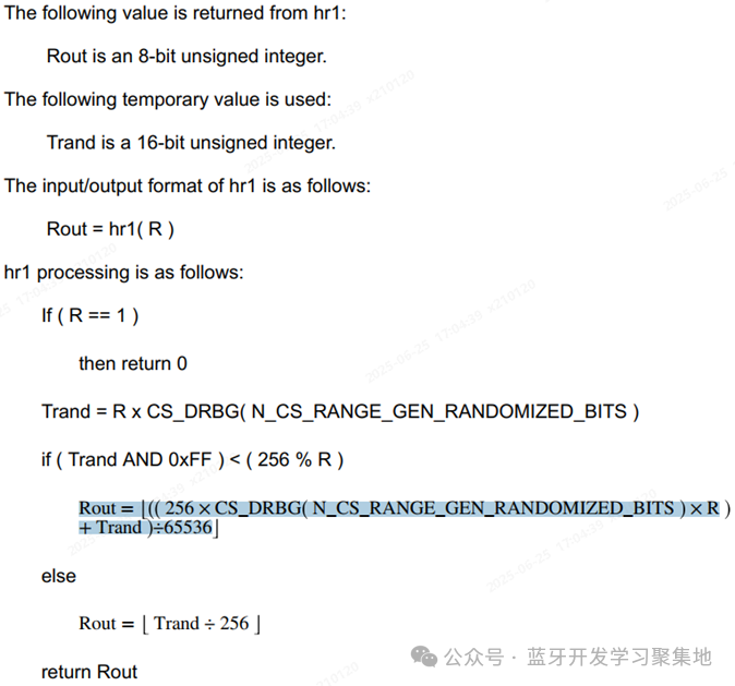
N_CS_RANGE_GEN_RANDOMIZED_BITS is the number of random bits used to perform the randomization seed process, which is fixed at 8 bits.
The CS random number generation function hr1 is used to generate random numbers within any range. The input to hr1 is an 8-bit unsigned integer R, representing any range of random numbers to be generated from 0 to R-1. This value should be greater than 0 and less than or equal to 255.The implementation process of the hr1 function: