1. Overview of the Overall Design Scheme
This design uses the STM32F103C8T6 as the main control chip, employing the HC-05 Bluetooth module to achieve wireless audio reception. The VS1053B audio decoding chip is used for MP3 format decoding, combined with button control and LED status indication, to construct a low-cost clone Bluetooth headset system. The hardware cost is controlled within 50 yuan, and the main functions include Bluetooth pairing, music play/pause, volume adjustment, and low battery indication.
2. Hardware Circuit Design
1. Core Module Selection
• Main Control Unit: STM32F103C8T6 (72MHz, 64KB Flash, 20KB RAM) • Bluetooth Module: HC-05 (Bluetooth V2.0 protocol, supports UART interface, powered by 3.3V/5V) (Communication between mobile phone and microcontroller based on HC-05 Bluetooth module)
• Audio Decoding: VS1053B (supports MP3/WMA decoding, SPI interface, DAC output) (Audio processing development guide based on STM32 controlling VS1053B chip) • Power Management: TP4056 (Lithium battery charging) + XL6009 (3.7V to 5V) + AMS1117-3.3V (5V to 3.3V)
2. Circuit Schematic Design
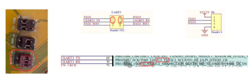

Figure: Shows the interface definitions and wiring relationships between the STM32 development board and various modules, including UART3 (PA9/PA10) connected to HC-05, and SPI1 (PB3/PB4/PB5) connected to VS1053B.
3. Key Module Circuits
• Bluetooth Interface Circuit: The TX/RX of HC-05 is connected to PA10/PA9 (USART1) of STM32, powered by 3.3V, and it is important to use a 1kΩ resistor for level matching (STM32 Bluetooth module circuit connection).
• Audio Output Circuit: The LINEOUT_R/L pins of VS1053B are connected to the TPA3116D2 amplifier module through a 220Ω resistor, driving a 4Ω/1W speaker.
• Power Circuit: Powered by two 18650 lithium batteries (7.4V), stepped down to 5V for the Bluetooth module and amplifier using MP2307, and then stepped down to 3.3V for STM32 and VS1053B using AMS1117.
3. Software System Implementation
1. Development Environment Configuration
• STM32CubeMX (initializing peripherals) + Keil5 (code writing and debugging)
• Library Version: STM32Cube HAL Library v1.8.0
• Debugging Tool: ST-Link V2
/** * @brief Bluetooth module initialization (including AT command configuration)
* @param none * @retval Initialization success (1: success 0: failure)
**/
uint8_t HC05_Init(void)
{
uint8_t retry = 0;
USART1_Init(38400); // AT mode baud rate fixed at 38400
HAL_Delay(100); // Test module connection
while(retry < 3)
{
HC05_SendCmd(“AT\r\n”, “OK”, 50);
if(HC05_ReceiveFlag) return 1; retry++;
}
// Configure working parameters (name/baud rate/role)
HC05_SendCmd(“AT+NAME=Shanzhai_BT\r\n”, “OK”, 100); // Set device name HC05_SendCmd(“AT+UART=9600,0,0\r\n”, “OK”, 100); // Working baud rate 9600 HC05_SendCmd(“AT+ROLE=0\r\n”, “OK”, 100); // Slave mode
USART1_Init(9600); // Switch to working baud rate return 0;
}
/** * @brief VS1053B audio decoding initialization
* @param none * @retval none */
void VS1053_Init(void) { VS1053_Reset(); // Hardware reset
VS1053_WriteReg(0x00, 0x0800); // Soft reset
HAL_Delay(100);
VS1053_WriteReg(0x0B, 0x0000); // Set volume (0x0000 is maximum)
VS1053_WriteReg(0x05, 0x0000); // Set working mode (MP3 decoding)
}
/** * @brief Audio data processing task (DMA transfer)
* @param data: audio data stream address len: data length
* @retval none
*/
void Audio_Process(uint8_t *data, uint16_t len)
{
while(!HAL_GPIO_ReadPin(GPIOA, GPIO_PIN_3));//Wait for DREQ to be high (chip ready) HAL_SPI_Transmit_DMA(&hspi1, data, len); // DMA transfer audio data
}
3. Main Program Flowchart
int main(void)
{
HAL_Init();
SystemClock_Config(); // Configure system clock to 72MHz
// Peripheral initialization
LED_Init(); // LED indicator
KEY_Init(); // Button (play/volume)
HC05_Init(); // Bluetooth module
VS1053_Init(); // Audio decoding
DMA_Init(); // SPI DMA configuration
while (1)
{
if(HC05_NewData)
{
// Received Bluetooth data
Audio_Process(HC05_RxBuf, HC05_RxLen);
HC05_NewData = 0;
}
// Button scanning
key_val = KEY_Scan(0);
if(key_val == 1)
{
// K1: Play/Pause
PlayState = !PlayState;
LED_Toggle(LED_PLAY);
}
else if(key_val == 2)
{
// K2: Volume +
Volume += 0x10;
if(Volume > 0xFE)
{
Volume = 0xFE;
VS1053_SetVol(Volume);
}
}
}
4. Bluetooth Audio Reception Interrupt Handling
C
/** * @brief USART1 interrupt service function (Bluetooth data reception)
* @param none
* @retval none
*/
void USART1_IRQHandler(void)
{
static uint16_t rx_ptr = 0;
uint8_t temp;
if(__HAL_UART_GET_FLAG(&huart1, UART_FLAG_RXNE) != RESET)
{
HAL_UART_Receive(&huart1, &temp, 1, 0); // Circular buffer processing
HC05_RxBuf[rx_ptr++] = temp;
if(rx_ptr >= HC05_BUF_LEN)
{
rx_ptr = 0;
HC05_NewData = 1; // Set data ready flag
HC05_RxLen = HC05_BUF_LEN;
}
__HAL_UART_CLEAR_FLAG(&huart1, UART_FLAG_RXNE);
}
}
4. System Debugging and Optimization
1. Troubleshooting Bluetooth Pairing Issues
• If the mobile phone cannot find the device, check the state of the HC05’s STATE pin: fast flashing indicates not connected, slow flashing indicates AT mode.
• The default pairing password is “1234”, which can be modified using the AT+PSWD command (A beginner’s guide to HC-05 Bluetooth module communication with STM32). 2. Audio Distortion Handling
• The SPI communication rate of VS1053B should be controlled below 10MHz, which can be achieved by modifying the SPI prescaler.
• Call VS1053_SoftReset() to clear the decoder’s internal buffer before audio data transmission.
3. Power Consumption Optimization Measures
• Enter low power mode when not paired (STM32 enters STOP mode, current <5mA)
• Mute the DAC output of VS1053B when audio is paused (set mute using 0x0B register)
6. Design Summary and Outlook
This design achieves the core functions of a Bluetooth headset through a modular architecture, with a cost only 1/5 of the original product. Future optimization directions include: adding a TPA3116D2 amplifier module to increase output power to 10W, porting FreeRTOS for multitasking scheduling (Bluetooth communication/audio processing/button scanning in parallel).
Adding an MFRC522 module to support NFC quick pairing
Note: This design represents personal views and should not be used for commercial purposes; it is provided for personal reference only!
If you have any questions or corrections, please follow my public account for updates
Feel free to contact me privately, and further development can be carried out based on this!