After publishing the teardown article, I often receive messages from friends asking how to learn electronic design, how to learn microcontrollers, and so on.
Many people feel confused and are unsure about what they should learn.
Some people know what they need to learn but don’t know where to start.
Only a very few can quickly clarify their learning direction, find suitable methods, continuously accumulate knowledge, and eventually become industry experts.
I have also gone through a similar phase. Before entering university, I stumbled upon the concept of “microcontroller”. After starting university, I began to browse various books related to microcontrollers in the library. In my first and second years, I mainly studied the 51 microcontroller, and by my third and fourth years, while participating in electronic design competitions, I started to work with the STM32 microcontroller. The learning process was quite bumpy; I read a bit from this book, some from that book, learned a little from this development board’s examples, and imitated a segment from that open-source project.
Compared to my classmates, I seemed to be “knowledgeable”, but how many of them had heard of microcontrollers? How many knew about STM32? How many had personally lit up a running light? It’s not that there were none, but indeed very few.
However, when it came to competitions, trying to complete a full project left me at a loss. Not only did I need to determine the overall plan and draw the schematic, but I also had to quickly finish the soldering and write a complete set of project code—this was no longer as simple as lighting up an LED or implementing a serial communication. It might require collecting data through I2C or SPI, processing information from serial ports or other interfaces, performing calculations on the microcontroller, and then outputting results to actuators like motors, servos, LEDs, or seven-segment displays. How to coordinate so many peripherals? How to arrange the timing of the code? In just a few days of competition, it was impossible to master so much content, and the result was naturally failure.
Therefore, if you want to truly get started in electronic development or embedded development, learning some basic peripherals with a development board is certainly helpful, but to complete a comprehensive project, you must train yourself with a more systematic and practical project.
Indeed, the best way to learn is by completing a real project. You will inevitably encounter many unknown knowledge points, and it will be like looking up words in a dictionary, tackling them one by one. When you have gone through the ups and downs and finally completed a full project, looking back at similar projects will seem much less daunting.
Based on this philosophy, we launched the quadrotor drone project in 2016. By designing the hardware, soldering, debugging, and writing the flight control program, we ultimately made the quadrotor drone take off, thus achieving our learning objectives.
This project is called Dragonfly Quadrotor Drone Project.
The Dragonfly V2 quadrotor drone project includes a complete quadrotor drone kit that is ready to fly, along with a series of supporting software and hardware courses, making it a comprehensive learning project.
If you are interested, you can also check out the quadrotor drone solutions on the website below, which are very helpful!
Selected 20 articles on STM32-based quadrotor drone circuit design solutions
1. Quadrotor Drone Kit
The quadrotor drone kit includes the quadrotor drone, a 2.4G communication remote controller, an e-Link32 programmer, batteries, chargers, and other necessary hardware components.
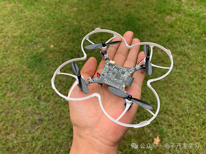
The quadrotor drone’s main hardware configuration is as follows:Main Control Chip:STM32F411CEU6, ARM Cortex-M4 core, 100MHz main frequency.Attitude Sensor:MPU6500Barometer:SPL06Wireless Communication:SI24R1Wireless Parameter Tuning:ESP8266-12FPower:720 hollow cup motorStatus Indicator Light:Single bus RGB LED full-color light
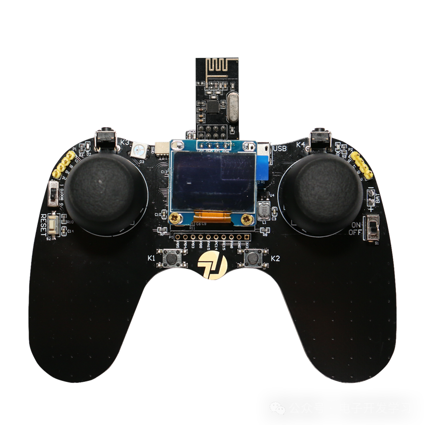
The 2.4G communication remote controller’s main hardware configuration is as follows:Main Control Chip:CH32F103C8T6Wireless Communication:SI24R1 moduleDisplay:0.96-inch yellow-blue dual-color OLED, resolution 128*64Joystick:Throttle joystick (does not return to center), direction joystick returns to center in all directionsButtons:4 buttonsExpansion:All remaining IOs are brought out, allowing it to be used as a development board.
The quadrotor drone uses the STM32F411CEU6, while the remote controller uses the CH32F103C8T6, so through this project, one can learn about the STM32F4 microcontroller and also gain some understanding and usage of domestic microcontrollers.
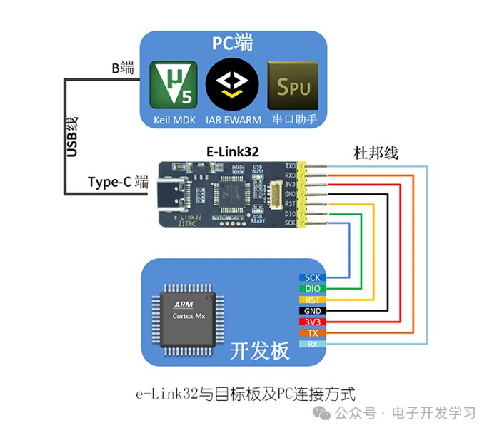
e-Link32 debugger and its connection method.e-Link32 is a high-quality DAP emulator that can debug all ARM Cortex-M core microcontrollers.
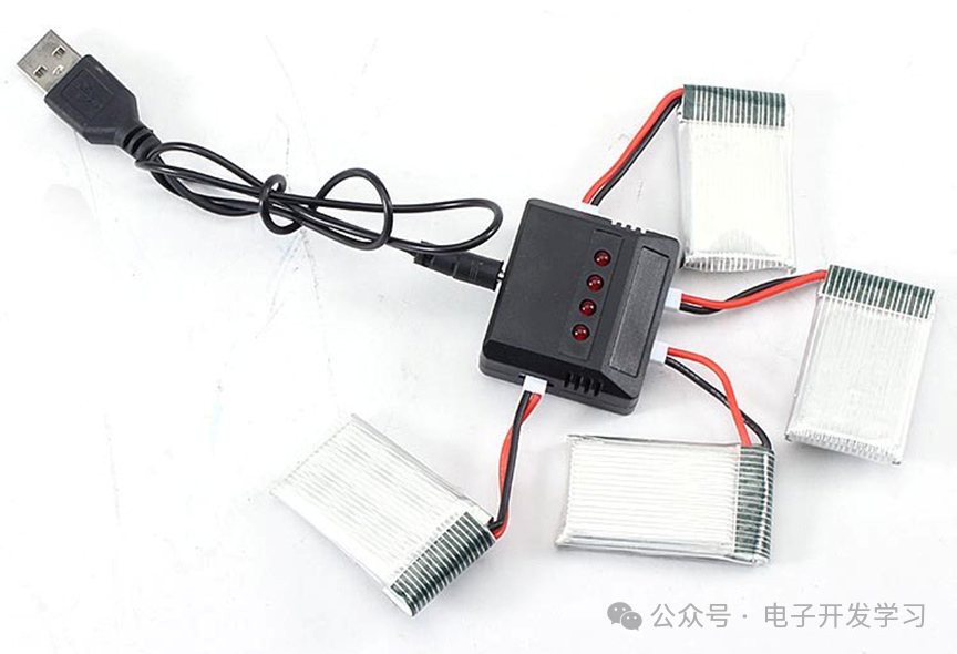
A one-to-four lithium battery charger that can charge four drone lithium batteries simultaneously.
END
Note: The cover image of this article comes from freepik, self-made by the author, and publicly available media, all authorized.
Industry Community