Since the launch of the Raspberry Pi Pico, many innovative applications have emerged. The RP2040 features a dual-core Arm Cortex M0+ processor, capable of running at clock speeds of up to 133MHz or even higher, and comes with a rich set of peripherals such as SPI, I2C, and up to 16 PWM signals, making it suitable for creating robots and drones.Many enthusiasts have made attempts, and here I have compiled some drone-related project attempts for friends planning to make flying machines, smart cars, or robots.The reference designs have been summarized on Electronic Forest, and you can copy the link to view: https://www.eetree.cn/project/657Reference Design 1The first article published on Tomshardwhare.com:Raspberry Pi Pico Drone Takes Flight (https://www.tomshardware.com/news/raspberry-pi-pico-drone)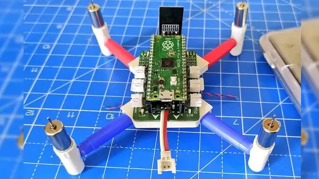 This flying machine, known as PiWings, is a quadcopter project powered by the Raspberry Pi Pico, developed by manufacturer Ravi Butani. It includes a custom PCB, Raspberry Pi Pico, and an Android-based control application. It can support a 6-axis IMU (Inertial Measurement Unit) for measuring direction and acceleration, a barometric module for measuring air pressure, four servos, and six ultra-small SOT23 packaged MOSFETs to drive motors requiring 3A current, which is much more than what common motor controllers like MX1508 or L9110S can safely provide. If you want to add your own components to the drone, you can do so via I2C or SPI sensors, just ensure balance and monitor weight to ensure stable flight.The firmware for this project was created from scratch by Butani with a simple idea; the project is not limited to four motors and can scale from helicopters to six-axis helicopters and even hovercrafts. If you prefer airplanes, this project can also be used for fixed-wing drones.Thanks to the included Android application, even the control setup is easy to use. This makes it possible to drive and maneuver the Pico-powered aircraft using the touchscreen of an Android device.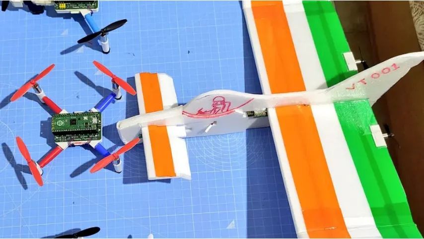
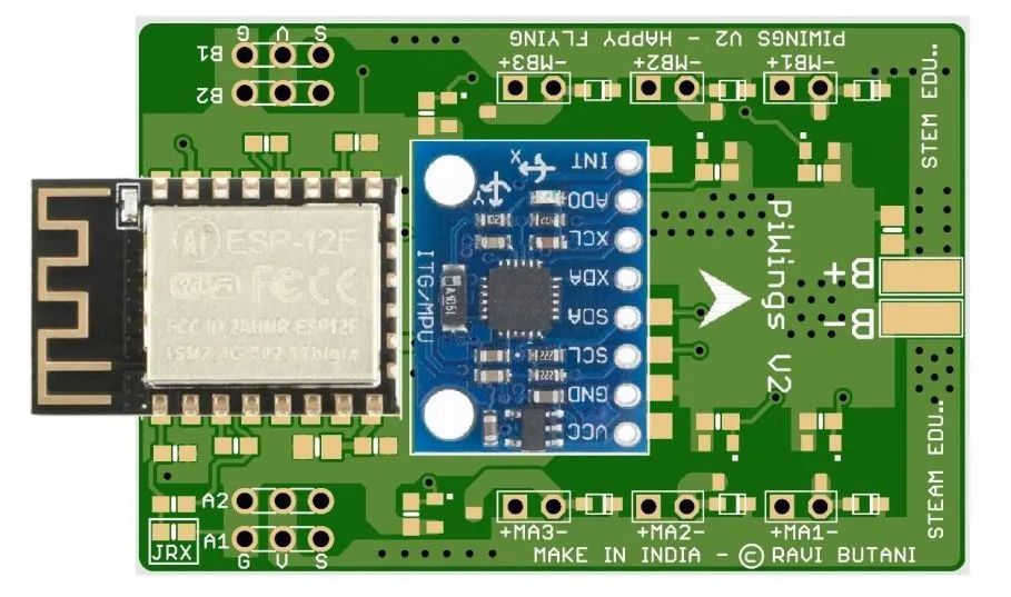
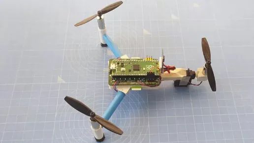 Later updates to PiWings V2 added an ESP-12F module for WiFi connectivity. The PiWings V2 controller is fully programmable for various devices. It uses a 4A coreless motor driver, supports up to four servos, has an onboard 6-axis IMU module, and built-in Wi-Fi support. There are also options for external iBUS RX modules and I2C sensors. Here are two images of the PCB for this version: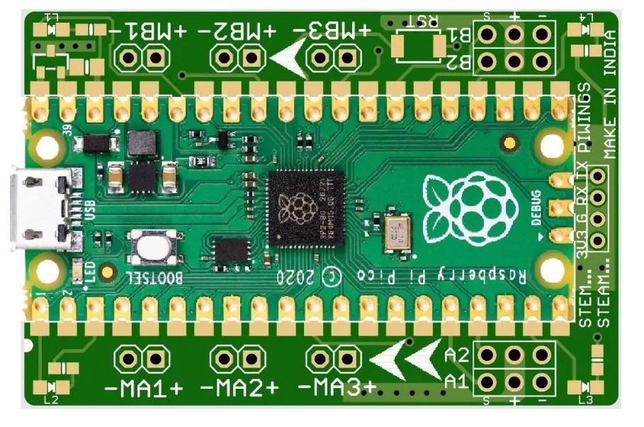
 Reference Design 2Additionally, an article on the website https://robu.in/ introduces the process of using the Pico to create a micro flying machine:DIY Raspberry Pi Pico Drone – The Hardware (https://robu.in/diy-raspberry-pi-pico-drone-the-hardware/)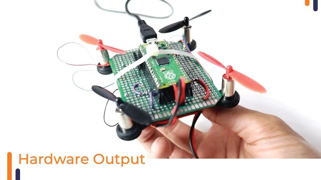
The final appearance
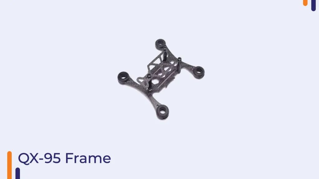
Before we understand the various parts of building a drone, let’s first look at the components we choose to build the drone.1)Frame:The frame, motors, and propellers for this drone are taken from the Qx95 kit available on robu.in, but you can choose your preferred frame or better yet, design it and have it 3D printed through robu.in’s 3D printing service.
When designing the frame, several factors need to be considered. The frame must be
-
Light – Obviously, the lighter it is, the easier it is to lift!
-
Sturdy – Quadcopters tend to fall a lot, so if it doesn’t break every time it falls – that’s a huge advantage.
-
Vibration-resistant – Otherwise, it may become unstable due to significant motor vibrations. This also helps reduce noise picked up by the accelerometer.
2)Motors:
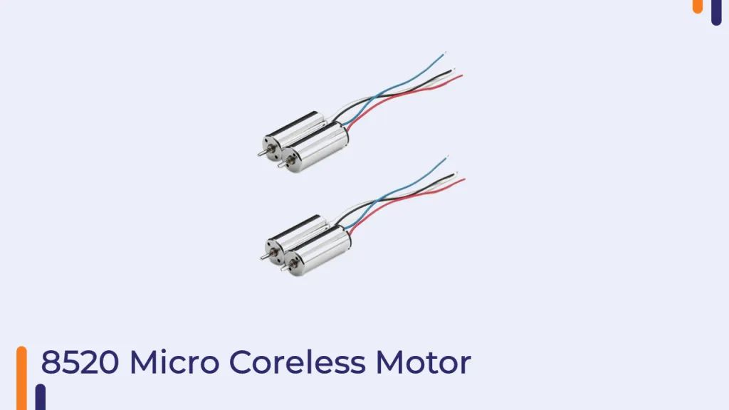
The most important things to look for when purchasing a motor set (from most important to less important) are
-
Type – Brushed DC and brushless AC motors. Nano quadcopters are usually based on brushed DC motors as they are smaller and easier to control without additional AC controllers. However, their thrust is much lower and cannot be used for larger quadcopters.
-
Can diameter – The 3D design is tailored for motors with a diameter of 8.5mm. The design must be adjusted for different diameters.
-
Maximum static thrust or simply thrust – Defines how much weight the motor can keep in the air, or basically – how heavy your quadcopter can be. The type of propeller must be defined, and thrust vs. current curves (commonly referred to as performance curves) are usually provided.
-
Weight – The weight of the motor will add to the total weight of the quadcopter. MMW and Hubson motors weigh about 5 grams each.
-
Load current – Defines the current consumed by the motor when the specified voltage is applied with the specified propeller. Note that if the propeller is not connected, this current will drop to a very small value, so always keep the propeller on when testing the cutoff voltage (which will be detailed later).
-
Recommended propeller size – Motors should target 55mm propellers.
-
Lifetime rating – This defines how long the motor should run without failure. Therefore, buying two sets of motors is always a good idea.
-
Speed – Faster speeds will give you quicker flight, but with increased current, thus requiring better batteries. Additionally, due to speed, they may be harder to control… hence the motors are designed for quadcopters.
3)Propellers
The differences in propellers are:
-
Length – Measured as radius times 2.
-
Number of blades – This is usually 2, but other blades can have 3 or more.
-
Shape of the propeller –
-
Twist angle – The steeper the angle, the more thrust the propeller can provide.
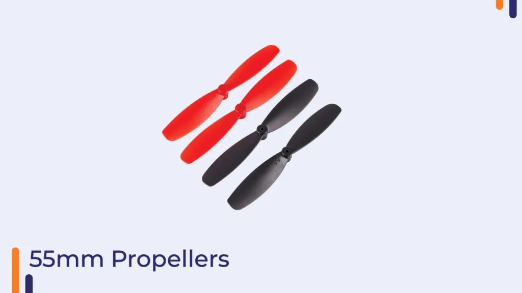
4)Batteries
Selecting the right battery is very important because the wrong battery will not allow the motors to draw enough current to power the quadcopter and, most importantly, will cause a significant voltage drop that will constantly interfere with the electronics. When purchasing, pay attention to the following:
-
Type – There are many types of batteries, such as lithium polymer, lithium-ion, and even those with different tones. Recently, graphene-based batteries have emerged, which can withstand higher currents and have higher capacity densities. Of course, the downside is the price!
-
Capacity (in mAh or Wh) – This will determine how much energy is stored inside the battery. The larger the capacity, the longer the quadcopter can run on a single charge. This will be proportional to the size and weight of the battery and will also determine how much current can be drawn from the battery.
-
Maximum allowable discharge (burst) and average discharge (constant) rates (C) – The former determines the peak current, such as when the quadcopter starts to accelerate, while the latter determines the normal operating current, such as when the quadcopter maintains a constant in the air. There is typically a rule of thumb that multiplying capacity by discharge rate will give the current the battery can provide. For safety, a 20% safety margin is also needed – we don’t want the battery to explode, do we? So, for example, if your battery has 200 mAh and 20 C average/constant discharge, then 200mAh * 25C * 80% = 4A. Therefore, on average, such a battery can easily provide 4A of current. However, this is just a rule of thumb, and when it comes to very high currents, we want a higher discharge rate, regardless of battery capacity.
-
Weight (g) – The larger the capacity, the heavier the battery will be, so you need to find a battery that provides enough flight time while also providing good flight performance.
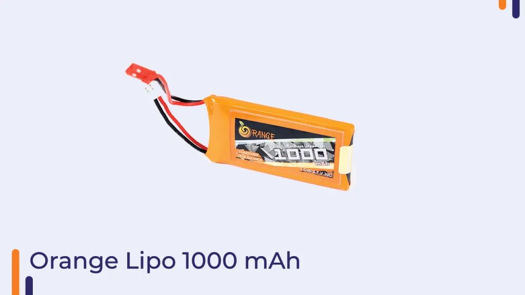
5) N-channel MOSFET
We need 4x MOSFET transistors, also known as switches, to work with PWM to provide peak current to the motors. Choosing them can be tricky, and there are several points to consider when selecting one for our application:
-
The maximum drain current (Id max) it can provide should be around 3A to support motors that can consume about 2.75A of current.
-
The Vgs threshold voltage must be low, possibly around 1V, as the lithium battery voltage may drop to 3.4V at some point. It’s best to also check the dependence of drain current (Id) on the threshold voltage (Vgs threshold) since each transistor will have different responses.
-
This is provided at a certain gate to absorb the bias Vgs. Usually, it is expected to be about 0.032 ohms, but the lower, the better. If you select a MOSFET with Rds (on) equal to about 0.3 Ohm, the voltage drop across the MOSFET will be 0.9V when the motor runs at 3A, meaning the motor will not receive enough voltage drop.
-
I used the si 2302 N-channel MOSFET in the circuit because it meets all these requirements.
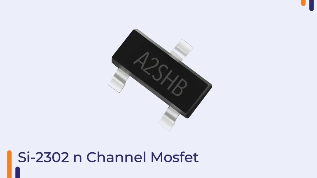
6) MPU6050 Accelerometer
When using an IMU to control the quadcopter, two tricky issues arise:
-
Ability to hover at a constant height. Typically, control of the Z-axis (vertical) is done by increasing or decreasing the desired speed of all motors, effectively increasing the offset. However, as the battery drains throughout the flight, even if the desired speed may not change, the voltage on the battery will drop, thus reducing speed.
-
Automatic takeoff and landing without user interaction. This can control the quadcopter as usual or perform an emergency landing when the battery is low. After the quadcopter reaches the ground, this can also be used to completely shut off the motors.
-
I used the MPU6050 accelerometer for our multirotor as it seemed to be the most viable.
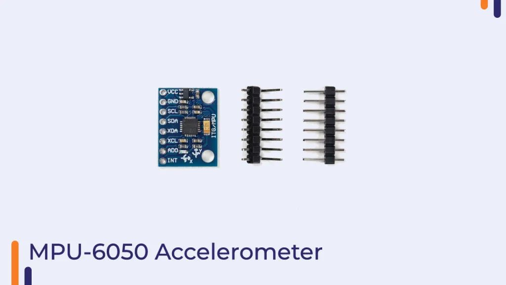
7) RX2A Receiver
I have used the RX2A receiver because it is very small, and the benefit of using the I-bus protocol is a plus for me.
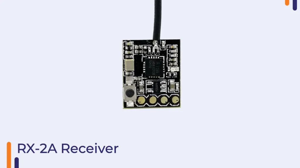
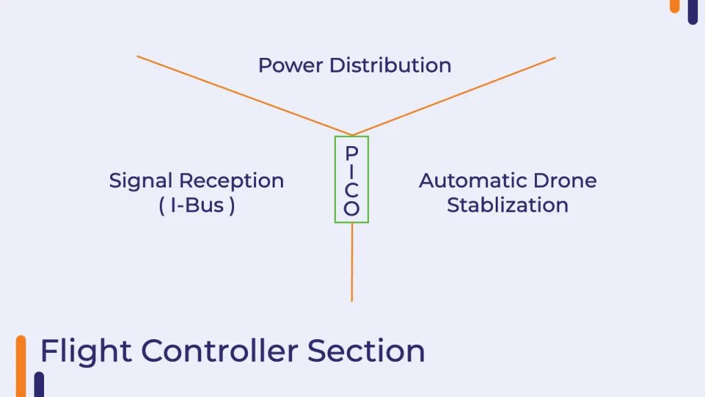
The control of the PICO is divided into three parts
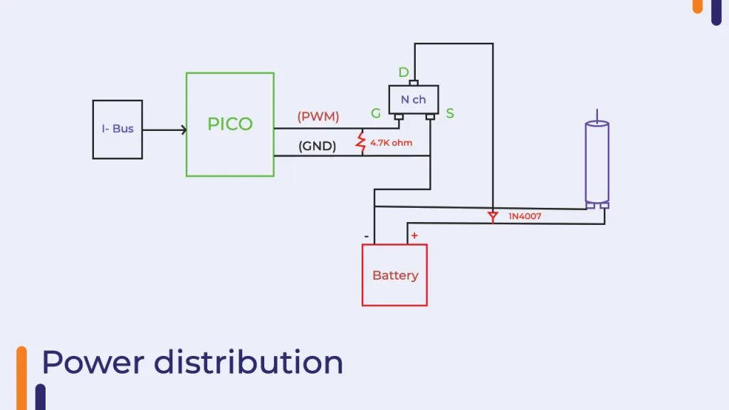
Power supply section
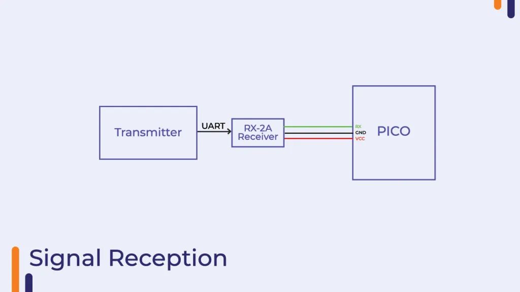
Signal receiving section
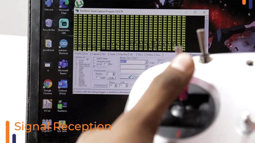
Information display interface receiving control signals sent from the transmitter
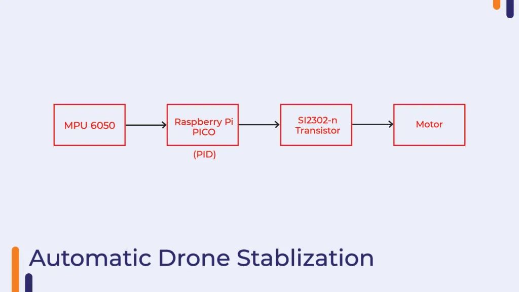
Auto-stabilization section
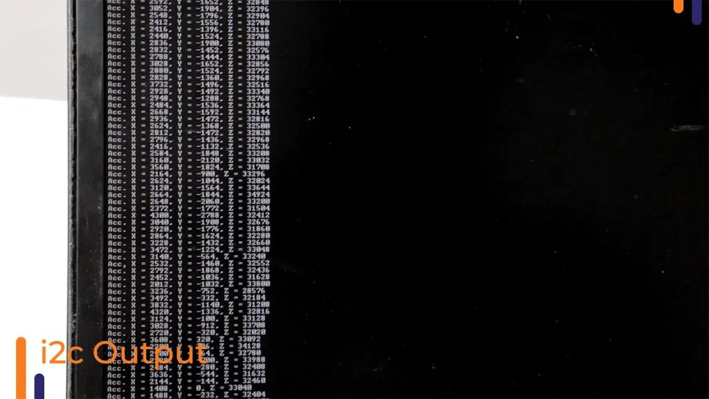
Information output from the attitude sensor
Additionally, there are articles on how to use the Raspberry Pi Pico with MicroPython programming to get all peripherals working; interested friends can click “Read the Original” to view.