Background Knowledge
The HC-SR04 ultrasonic module is a commonly used distance measurement module, widely applied in obstacle-avoiding robots, smart homes, and other fields due to its low cost, high accuracy, and ease of use. Below is a detailed introduction to it:
【Basic Structure】
The HC-SR04 module mainly consists of an ultrasonic transmission circuit, an ultrasonic reception circuit, a control and signal processing circuit, and a power supply circuit. It has two piezoelectric ceramic ultrasonic sensors, one for transmitting ultrasonic signals and the other for receiving reflected ultrasonic signals, along with an external signal processing circuit.
【Pin Definitions】
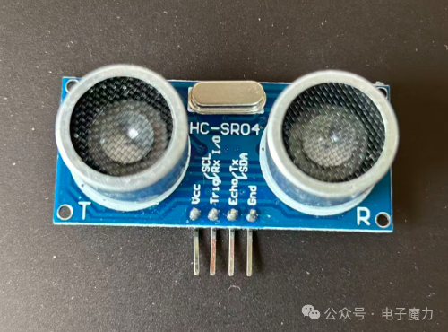
The module has a total of 4 pins, including 2 power pins and 2 control pins. They are as follows:
-
VCC: Connects to a 5V DC power supply to power the module.
-
GND: Power reference ground, must be connected to the controller’s ground.
-
Trig: Trigger signal input pin, receives control signals from the microcontroller, initially set to low level, and operates when a high level is detected; can be connected to any IO port.
-
Echo: Echo signal output pin, used to send distance measurement results to the microcontroller; can be connected to any IO port.
【Main Parameters】
-
Operating Voltage: DC 4.5V-5.5V, typical value is 5V.
-
Operating Current: Typical value during measurement is 15mA, maximum value is 20mA.
-
Measurement Range: 2cm-400cm.
-
Measurement Accuracy: ±3mm.
-
Operating Frequency: 40kHz±1kHz.
-
Measurement Angle: ≤15° cone angle.
-
Module Size: 45mm×20mm×15mm.
【Working Principle】
The module triggers distance measurement through the IO port. When the Trig pin receives a high-level pulse of at least 10μs, it emits 8 ultrasonic pulses at 40kHz. The ultrasonic signal propagates through the air, reflects off obstacles, and is captured by the receiving sensor. At this time, the Echo pin outputs a high level, and the duration of the high level corresponds to the time taken for the ultrasonic wave to travel from transmission to reception. By calculating this time difference and combining it with the speed of sound in air (typically 340m/s), the distance to the obstacle can be determined using the formula: Distance = High Level Time × Sound Speed / 2.
【Application Scenarios】
-
Obstacle-Avoiding Robots: Can be installed on robots to detect the distance to obstacles, enabling obstacle avoidance control.
-
Smart Homes: Used for human detection and distance measurement, such as detecting a person’s approach to trigger door opening actions, or for indoor distance measurement and triggering automatic lighting, etc.
1. Electronic Components Used in the Experiment
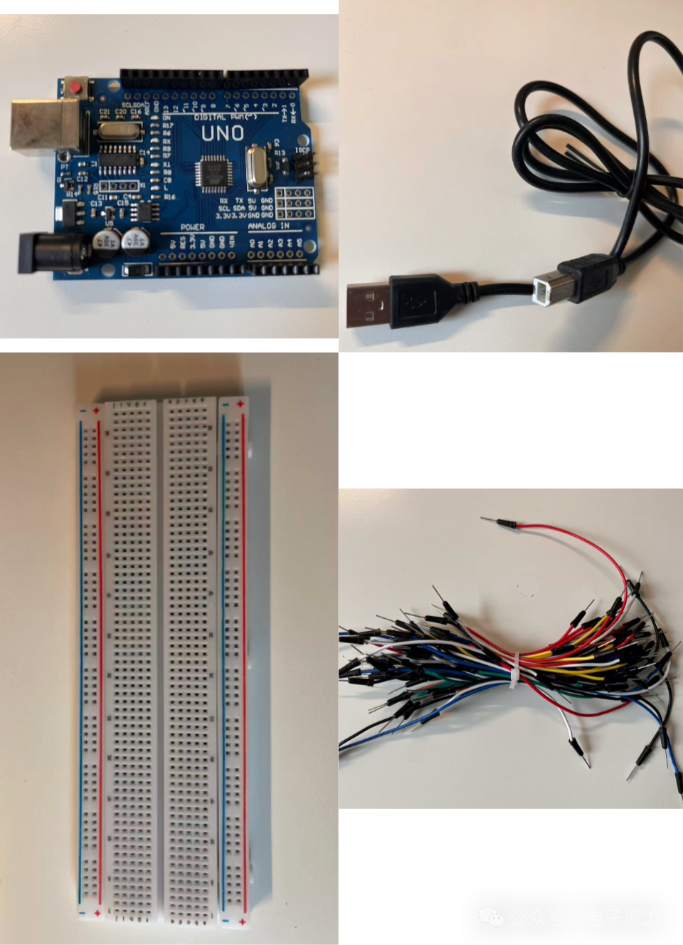
1 Arduino board, 1 USB data download cable, 1 breadboard, several Dupont wires
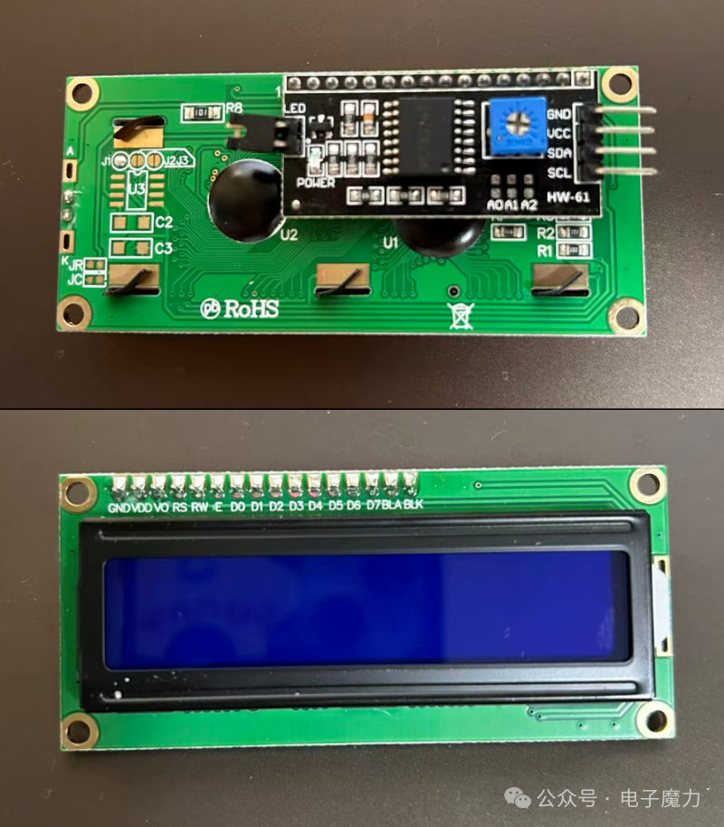
1 LCD1602 IIC LCD display (with integrated driver circuit)
1 HC-SR04 ultrasonic module
2. Experimental Steps
We will connect the components as follows:
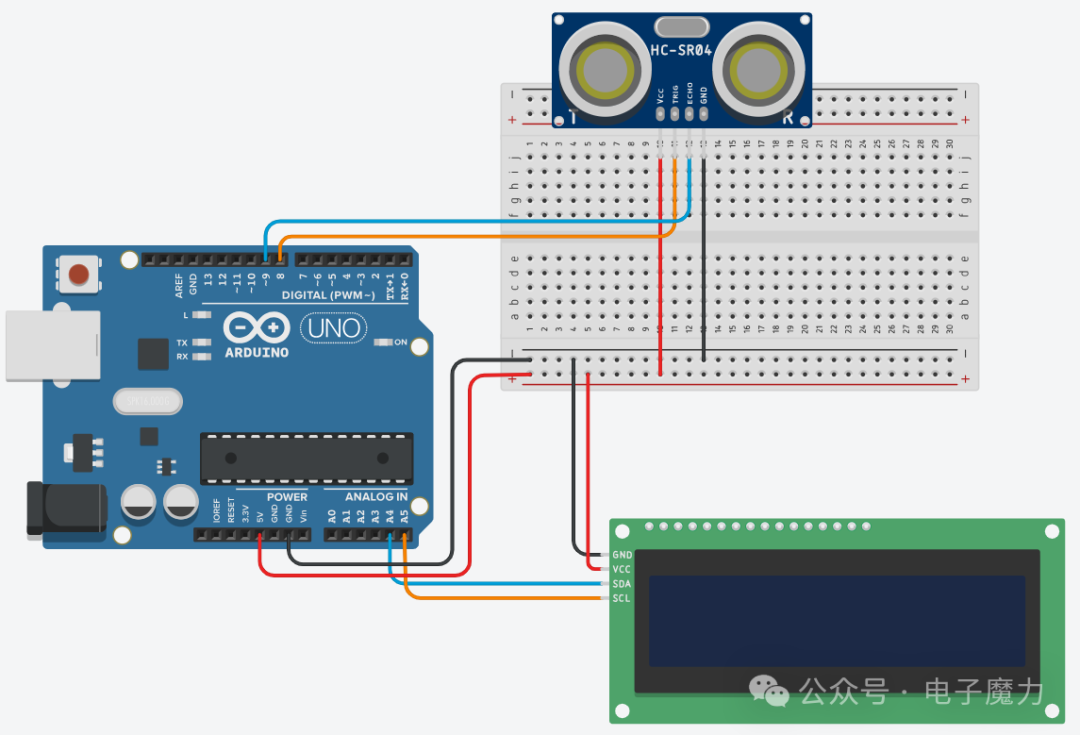
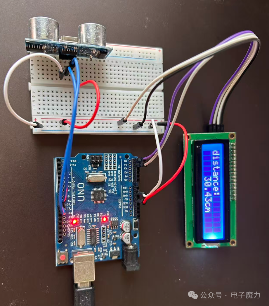
The VCC and GND of the ultrasonic module are connected to the common positive and negative terminals of the breadboard, and the Trig and Echo pins are connected to digital pins 8 and 9 of the Arduino mainboard;
The VCC and GND of the LCD screen are connected to the common positive and negative terminals of the breadboard, and the SDA and SCL pins are connected to analog pins A4 and A5 of the Arduino mainboard;
The common positive and negative terminals of the breadboard are connected to the 5V and GND of the Arduino mainboard;
3. Program Code
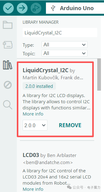
This experiment’s code requires the inclusion of the LiquidCrystal_I2C.h third-party library to drive the LCD1602 display; search for and install this library in the IDE.
#include <LiquidCrystal_I2C.h>  // LCD1602 screen driver library
LiquidCrystal_I2C lcd(0x27, 16, 2);  // Set LCD1602 device address 0x27, 16 columns 2 rows
const int TrigPin = 8;  // Define the Trig pin of the ultrasonic module
const int EchoPin = 9;  // Define the Echo pin of the ultrasonic module
float distance;         // Define distance variable
void setup() {  lcd.init();                // Initialize lcd  lcd.backlight();           // Turn on lcd backlight  pinMode(TrigPin, OUTPUT);  // Set output mode  pinMode(EchoPin, INPUT);   // Set to input mode to detect pulse width on the pin}
void loop() {  // Generate a 10us high pulse to trigger TrigPin  digitalWrite(TrigPin, LOW);  delayMicroseconds(2);  // Delay 2ms  digitalWrite(TrigPin, HIGH);  delayMicroseconds(10);  // Delay 10ms  digitalWrite(TrigPin, LOW);
  distance = pulseIn(EchoPin, HIGH) / 58.00;  // Detect pulse width and assign the measured distance to the distance variable  lcd.setCursor(0, 0);                        // Set cursor to first line, first column  lcd.print("distance:");                     // Display string  lcd.setCursor(5, 1);                        // Set cursor to second line, sixth column  lcd.print(distance);                        // Display distance value on the LCD  lcd.print("cm");                            // Display string  delay(1000);                                // Delay  lcd.clear();                                // Clear screen}
4. Experimental Results
In this experiment, the ultrasonic module emits ultrasonic signals, which reflect off obstacles and return. When the ultrasonic wave receives the corresponding signal, it measures the distance between the obstacle and the ultrasonic module.
During ultrasonic measurement, the board should be placed flat on a level surface, and the obstacle should ideally be directly in front of the ultrasonic module. By moving the obstacle, different distances can be displayed on the LCD screen.
In the code, a 10us high pulse is first generated to trigger the TrigPin, causing the ultrasonic wave to emit 8 square wave signals at 40kHz, and then the Echo pin receives the square wave signal. The code line distance = pulseIn(EchoPin, HIGH) / 58.00 obtains the distance value in cm. Here, we see that pulseIn(EchoPin, HIGH) measures the time taken for the high-level pulse signal from emission to reception, and dividing by 58 converts it to distance (those interested in the specific conversion process can search for it themselves).
Wiring Diagram:
Experimental Video:
The code in this article has been uploaded to Gitee, see the link: https://gitee.com/webxiaohua/arduino-learn/tree/master/26_chao_sheng_bo_ce_ju