 1. Determine the Plan and Purpose
Hello everyone, based on customer requirements, today we will use Arduino to implement the data acquisition of a six-channel 10-bit ADC, with the goal of adapting the acquisition software to the Arduino ecosystem. The content requirements are as follows:
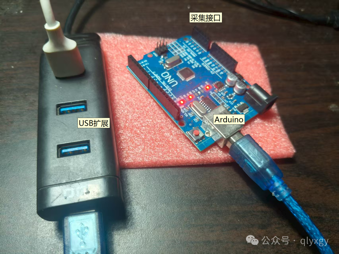
Objective: Integrate six-channel data acquisition with Arduino's internal ADC into acquisition software. 01. Build the Arduino main control program to achieve data acquisition and upload; 02. Build the LabVIEW lower-level driver to achieve hardware compatibility with Arduino; 03. Implement six-channel 10-bit ADC acquisition, with an overall polling rate requirement of 1ksps; Keywords: VISA, Serial Port, ADC, Arduino, LabVIEW, Analog Signal Acquisition. Note: High-definition images can be viewed via WeChat on mobile.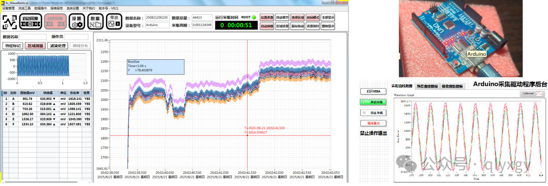 2. Arduino Acquisition Effect Demonstration3. Reference Code for Arduino
/*************************************************************************Arduino program for acquiring ADC voltage, collecting six channels, sending byte commands, one channel occupies two bytes, 2x6+2=14 bytes, start frame 0xAA, end frame is 0XFF*************************************************************************/#include <TimerOne.h>#define BUFFER_SIZE 128 char inputBuffer[BUFFER_SIZE]; // Buffer for received commandsint bufferIndex = 0; // Buffer indexconst int channels[] = {A0, A1, A2, A3, A4, A5}; // Define ADC channels to be usedconst int numChannels = 6; // Number of channelschar Flag_AdcLoopEn = 0;void setup(){ pinMode(13, OUTPUT); digitalWrite(13, LOW); Serial.begin(115200); // Initialize serial communication Timer1.initialize(1250); Timer1.attachInterrupt(UserTimeEvent); // blinkLED to run every 0.15 seconds}// Acquisition interrupt functionvoid UserTimeEvent(void){ Flag_AdcLoopEn = 1;}// Serial port receive interrupt handling functionvoid serialEvent(void){ while ( Serial.available() ) { char c = Serial.read(); inputBuffer[bufferIndex++] = c; // Handle newline or carriage return as the end of a command if (inputBuffer[bufferIndex - 1] == '\n' && inputBuffer[bufferIndex - 2] == '\r') { // Add end character to buffer inputBuffer[bufferIndex] = '\0'; digitalWrite(13, HIGH); // Reset buffer bufferIndex = 0; } if(bufferIndex>32)bufferIndex=0; // Handle newline or carriage return as the end of a command 【Command handling function omitted......】 }}void loop() { byte data[numChannels * 2 + 2]; // Create an array to store all data plus start and end frames // Set start frame data[0] = 0xAA; if (Flag_AdcLoopEn == 1) { for (int i = 0; i < numChannels; ++i) { int analogValue = analogRead(channels[i]); // Read the analog value of the current channel data[i * 2 + 1] = highByte(analogValue); // Place high byte into data stream data[i * 2 + 2] = lowByte(analogValue); // Place low byte into data stream } // Set end frame data[numChannels * 2 + 1] = 0xFF; // Send the entire data packet for (int i = 0; i <= numChannels * 2 + 1; ++i) { Serial.write(data[i]); } Flag_AdcLoopEn = 0; // Clear trigger flag }}01【Initialization】Set the serial port baud rate to 115200 in the setup() function.
02【Initialization】Set the interrupt timer in the setup() function to control the acquisition speed, serving as the time base for ADC acquisition.
03【Loop Section】The loop section (loop()) processes the flag for timer-triggered events to perform data acquisition;
04【Loop Section】Use the analogRead() function to sequentially read voltage values from each specified analog input port; use highByte() and lowByte() functions to split each reading into two bytes for a more accurate representation of the possible full range (0-1023) values.
05【Sending Logic】 Constructs a data packet containing the start flag 0xaa, data from all channels, and the end flag 0xff. Finally, this data packet is sent byte by byte via Serial.write().
06【Sending Logic】 If a direct delay(1) is used to update and send 1000 new data packets per second, it is inaccurate; if strict actual benchmarks are required, a timer should be used to achieve precise time base triggering;
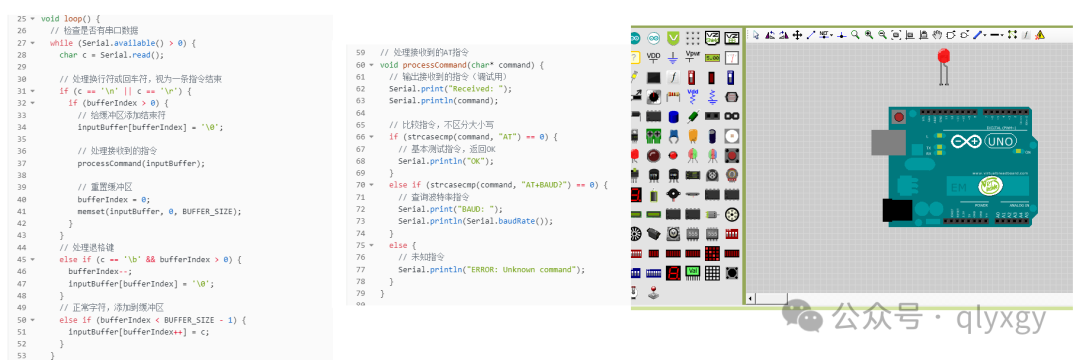
07 The above image is a reference for serial command code processing, it is recommended that both the upper and lower machines use serial port receive interrupts.
08 To ensure stable operation of serial port reception, the code needs to have end character recognition, length exceeding limits reset, and receive timeout reset mechanisms; CRC checks should be added if necessary;
 4. Upper Machine Software Section4.1 Software Main Interface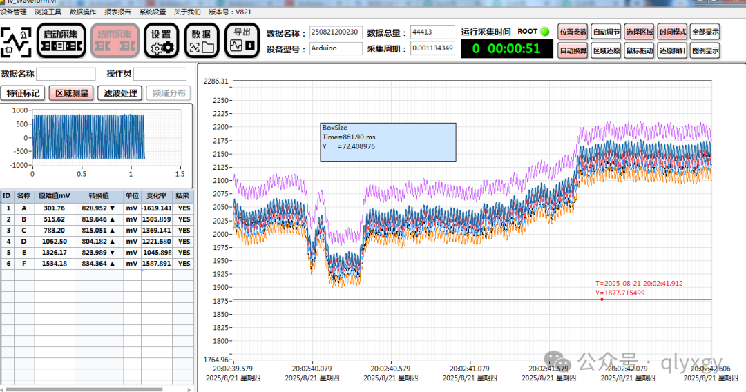
01【Acquisition Speed】At a baud rate of 115200 for six channels, ignoring ADC time, the time for one serial communication = 86us*(2+2*6)= about 1.2ms, which is basically consistent with the actual measurement shown in the above image.
02【Acquisition Accuracy】Theoretical accuracy is 5000/1024=4.88mV, increasing sliding filtering can further improve accuracy and smoothness;
03【Filter】Due to the single-ended main control chip’s internal ADC, frequency filtering processing is required;
4.2 Arduino Acquisition Interface Main Interface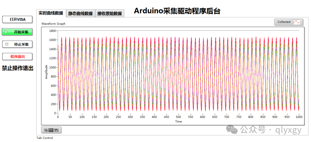
01【Driver Function】Responsible for controlling hardware for configuration, acquisition, and stopping operations,
02【Driver Function】Restores the acquired data to the original ADC voltage signal, then quantizes and uploads the data;
03【Data Processing】The Arduino has a 10-bit ADC, with 2 registers for one channel’s value; note that it can save bytes to reduce sending time, 6*10=60 bits=60/8=8 bytes, saving 4 bytes;
04【Data Quantization】One part displays data without storage, while another part sends it to the main interface for storage and further processing and display; note that the lower-level software must ensure reliable acquisition as a priority, simplifying display without consuming too many resources;
4.3 Arduino Data Acquisition Backend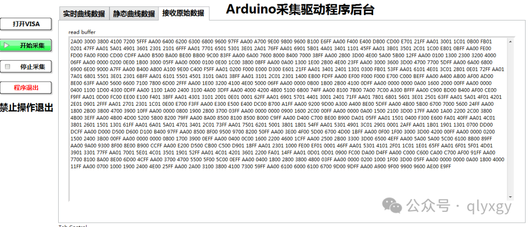
01【Communication Protocol】Data header 0xAA + channel data 2 bytes x 6ch + data tail 0xFF,
02【Notes】When sending data quickly, a single reception may contain multiple frames of data, and the header and tail data frames are likely to be incomplete; the core logic here is to separate the received data into original frames without wasting header and tail data;
03【Data Processing】Analyze the received data to extract valid frames; note that the first frame needs to be concatenated with the remaining data from the last time, and similarly, the remaining bytes from this time need to be concatenated with the next data reception’s front; this effectively avoids wasting header and tail data and reduces data loss rate;
04【Data Analysis】For more reliable data parsing, the frame header and tail are parsed in parallel, using 0xFF0xAA as the header and tail string; thus, a frame has four markers, improving data accuracy and interference; further data reliability requires adding CRC checks, and the parsed data is checked again for validity;
4.4 Arduino Device Opening Interface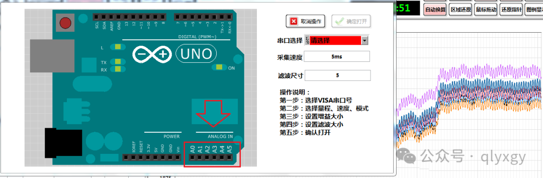
01【Acquisition Rate】is affected by the serial port baud rate and acquisition time; at a baud rate of 115200, six-channel acquisition can achieve 1ksps, while single-channel acquisition can exceed 5ksps.
02【Sliding Filter】The internal sliding filter of the software can improve acquisition accuracy and data quality through smoothing processing;
03【Serial Port Selection】Requires installation of hardware drivers; if the serial port number is not visible, try refreshing and selecting again;
04【Acquisition Target】The A0~A5 analog signal acquisition interfaces on the Arduino board are single-ended acquisitions to ground, with a 10-bit ADC and an accuracy of about 5mV;
5. LabVIEW Driver Code Overview(High-definition image)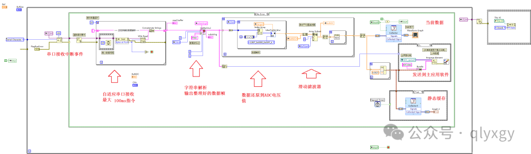
01【Serial Port Scheme】Using serial port events + serial port polling + separation parsing + sliding filtering acquisition scheme;
02【Serial Port Reception】Most designs use a single interrupt to read the number of bytes; this design uses a 10ms*10 times reading method, aiming to adapt to different lengths of data, so data exceeding 10ms will be concatenated together, similar to polling mode;
03【Data Concatenation】In fast acquisition cases, to ensure real-time acquisition, the priority of real-time processing must be lowered, so data concatenation saves processing time frequency for batch processing;
04【Data Analysis】FFAA is analyzed together as header and tail, which improves accuracy, but care must be taken as errors may occur if only one command is present;
05【Sliding Filter】The implementation method is to cache a two-dimensional array and then perform average filtering;
06【Data Quantization】One part has a data collector displaying quantization, while another part organizes the data and sends it to the main program application;
07【Logic in the Above Image】Serial port reception: using For loop + shift register + string cache;
08【Logic in the Above Image】Data parsing: input the current received string + input the last remaining unparsed string + recognition marker 0xFF0xAA = output classified and organized valid frames (1D array) + remaining unrecognized string (applied to the next analysis);
09【Logic in the Above Image】Sliding Filter: input cache 2D array + current 1D element, then extract the subset of the length to be filtered, and finally average process = the 1D element after this sliding processing;
6. Declaration01. All images, text, and designs in this tutorial are original, and the copyright belongs to Qianli Youxuan Teaching Base;02. This tutorial is for technical sharing, applied in the teaching field, and the related code and technical discussions are for reference only;03. Some images in this tutorial contain timestamp signals, which should be consistent with the publication date of this article;04. Note: Using the mobile WeChat client can view related high-definition images.;