Currently, encoders, as an important type of sensor, are playing an increasingly significant role in stage machinery applications. The precise movement of motion devices largely depends on the reliability of encoder installation, the stability of electrical signal transmission, and the accuracy of counting units. Encoders can be classified in various ways, the most common being incremental encoders and absolute encoders, with absolute encoders further divided into single-turn absolute encoders and multi-turn absolute encoders; based on different internal working principles, they can also be categorized as magnetic encoders and photoelectric encoders.
In the application of stage machinery, several issues often arise regarding the use of encoders. For instance, when dealing with a multi-axis driven lifting stage, what type of encoder should be chosen: an incremental encoder or an absolute encoder? Is it feasible to use a magnetic encoder from a cost perspective? This article analyzes how to select, install, and use encoders in stage machinery applications based on their technical characteristics.
1 Technical Characteristics
1.1
Encoder Principles
1.1
Encoder Principles
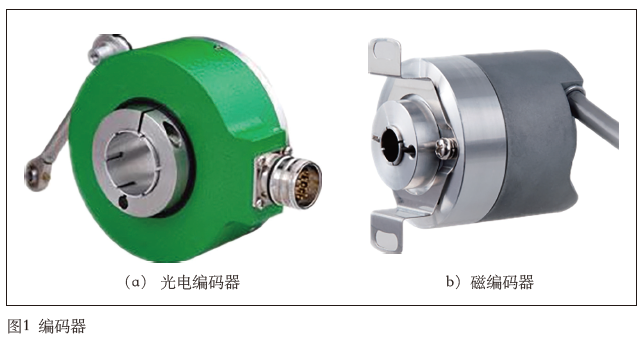
Encoders are mainly divided into two types based on their internal working principles: photoelectric encoders and magnetic encoders, as shown in Figure 1.
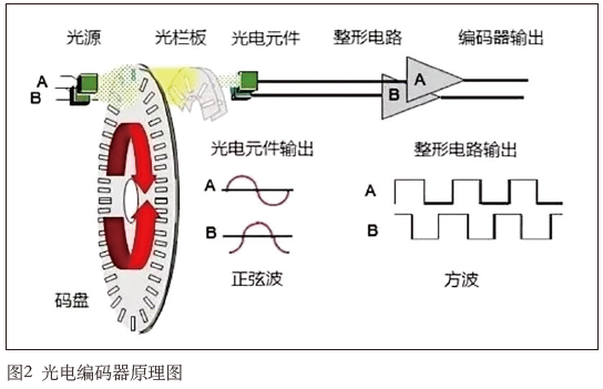
The main working principle of a photoelectric encoder is to convert the mechanical geometric displacement of the output shaft into pulse or digital signals through photoelectric conversion. It mainly consists of a grating disk and a photoelectric detection device, as shown in Figure 2. In a servo system, the grating disk is co-axial with the motor, allowing the motor’s rotation to drive the grating disk’s rotation. The photoelectric detection device then outputs several pulse signals, and the number of pulses per second can be used to calculate the current speed of the motor. The code disk of the photoelectric encoder outputs two phase-shifted light codes at 90°, allowing the motor’s rotation direction to be determined based on the changes in the output light code state of the dual-channel.
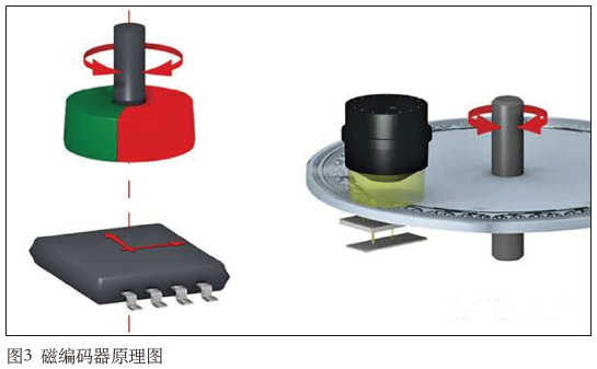
The structure of a magnetic encoder primarily includes a permanent magnet that generates a magnetic field installed at the end of the encoder’s rotating shaft, with a Hall sensor chip placed on a PCB. By approaching this permanent magnet according to certain requirements (direction and distance), as shown in Figure 3, the voltage signals output from the Hall sensor via the PCB can be analyzed to determine the rotational position of the encoder rotor.
1.2
Encoder Signal Output
1.2
Encoder Signal Output
Based on the type of signal output, encoders can generally be divided into incremental encoders and absolute encoders.
Incremental encoders have a wide range of applications, with the most common type being pulse output. They convert displacement into periodic electrical signals, which are then transformed into counting pulses, with the number of pulses indicating the magnitude of the displacement. Typically, they output A phase, B phase, and Z phase signals, where A phase and B phase are pulse outputs delayed by 1/4 cycle, allowing the determination of forward and reverse rotation based on the delay relationship. Additionally, by capturing the rising and falling edges of A phase and B phase, 2x or 4x frequency can be achieved; Z phase is a single-turn pulse, outputting one pulse per revolution.
Absolute encoders are further classified into single-turn absolute encoders and multi-turn absolute encoders, typically using communication methods to interact with PLCs or drive units, such as SSI, PROFINET, CANOPEN, etc. Single-turn absolute encoders generally record the absolute position for one rotation of the encoder, commonly used for components that perform single-turn rotational motion. Multi-turn encoders have a broader application range, capable of recording the actual number of revolutions the encoder has completed.
The methods for detecting multi-turn absolute encoders mainly include battery-powered counting registers and mechanical gear rotation encoding.
-
The principle of a battery-powered counting register is simple; it uses a microprocessor installed within the encoder to record, calculate, and store the number of rotations. The battery’s role is to ensure that the encoder can continue to accumulate and record the number of turns even when powered off.
-
The multi-turn encoder with mechanical gears contains a gear transmission structure similar to a clock’s gears, consisting of a series of reduction gears that mesh with the main mechanical shaft in successive stages, with each gear having an integer multiple reduction ratio relative to the previous gear and the main mechanical shaft. By identifying the rotational angle position of each gear, the number of revolutions of the main mechanical shaft can be detected. The absolute position feedback from the mechanical gear multi-turn encoder is based on the current mechanical physical transmission mechanism directly measured, rather than calculated from historical records, eliminating the need for a battery and being unaffected by external environmental factors like signal interference or programming errors, thus ensuring the safety of signal feedback from the source of position detection.
2 Installation and Use
2.1
Selection Issues
2.1
Selection Issues
Compared to traditional optical encoders, magnetic encoders do not require complex code disks and light sources, resulting in fewer components and a simpler detection structure. Additionally, Hall elements offer many advantages, such as robust structure, small size, lightweight, long lifespan, resistance to vibration, and immunity to contamination or corrosion from dust, oil, moisture, and salt mist.
Of course, magnetic encoders also have specific drawbacks, such as susceptibility to electromagnetic interference, necessitating compensation and protection measures to avoid temperature drift. Another significant issue is multi-turn position feedback. Using magnetic encoders for absolute position feedback requires adding information processing units and position memory units within the encoder, typically necessitating the addition of batteries for power-off retention. However, this method has certain usage defects, such as the loss of position in case of battery failure.
In the stage machinery industry, due to the prevalence of mechanical devices on-site, stability is usually prioritized, leading to the common selection of photoelectric encoders.
2.2
Installation Position
2.2
Installation Position
There are various installation methods for encoders, including those mounted on motor shafts, those mounted on reducer shafts, and other forms such as pull-wire installations.
Installing the encoder on the motor’s tail shaft is primarily to achieve speed closed-loop control. The inverter can calculate and obtain the current motion status of the motor in real-time through the encoder, enabling corresponding speed adjustments. For example, if the inverter aims for the motor to output a stable speed of 1,200 r/min, but the current actual speed is 1,150 r/min, the inverter can collect the encoder value on the motor’s tail shaft to determine that the motor’s actual speed has not reached 1,200 r/min, subsequently adjusting the current loop to increase the speed to 1,200 r/min. During this process, if the speed cannot be increased due to other reasons, the inverter will trigger an alarm. The benefits of using a speed closed-loop are numerous, as it allows the motor to maintain similar operating characteristics under different load conditions, which is advantageous for position loop adjustments.
In stage machinery applications, there is typically a requirement for a separate incremental encoder to be installed on the motor’s tail shaft for speed regulation, and this encoder is often also used for position regulation. For some devices that only have one encoder installed on the low-speed drive shaft, such as at the output position of the reducer, it is generally impossible to achieve a speed closed-loop, and only a rough position closed-loop can be completed, with both precision and response speed being insufficient, leading to discrepancies in response under varying load conditions.
For encoders installed on the motor’s tail shaft, there are typically small half-shaft sleeve encoders and through-hole encoders. Based on practical applications, both types of incremental encoders perform well, with encoder looseness and operational shaking being negligible. Either type can be used. However, for applications requiring a handwheel on the motor’s tail shaft, only through-hole encoders can be selected.
2.3
Dual Encoder Installation
2.3
Dual Encoder Installation
Dual encoders often use a combination of one incremental and one multi-turn absolute encoder, or two incremental configurations. The two encoders in a device usually serve different purposes, with the incremental encoder primarily used for speed loop adjustment (most inverters only support using incremental encoders for speed closed-loop, while a few also support multi-turn absolute encoders for speed loop adjustment); the second encoder is used for position adjustment.
To achieve a SIL3 safety level, dual encoders must be configured to compare the encoders, enabling quick detection of abnormalities in the equipment in the event of one encoder failure, preventing dangerous situations caused by the failure of a single encoder.
However, in certain applications, such as multiple motors driving the same rigid device, the configuration of incremental plus multi-turn absolute encoders is adopted, with the multi-turn absolute encoder generally installed at the execution position, such as using a pull-wire sensor or at the final output of the reducer for final position measurement and precise comparison of positions between multiple devices. In such cases, if a multi-turn absolute encoder is not installed, the incremental encoder may continuously accumulate errors, leading to deviations in the final positions among multiple drives, potentially causing equipment tilting or uneven force distribution.
Currently, dual-output encoders have emerged, where a single encoder can output two types of signals, one incremental and one multi-turn absolute, which can be conveniently installed on the motor’s tail shaft. However, this installation method may lead to simultaneous issues with both the incremental output signal and the multi-turn absolute output signal, such as anomalies due to shaft looseness affecting both encoder signals or abnormalities in the encoder’s internal power supply circuit causing both outputs to malfunction. To mitigate such issues, a separate encoder installation method can be used, placing the two encoders at different positions, such as an incremental encoder on the motor’s tail shaft and a multi-turn absolute encoder on the reducer shaft, etc.
3 Conclusion
In the application of stage machinery, there is no definitive conclusion regarding the selection of encoders; it is generally determined based on usage conditions which type of encoder to use. During the selection process, not only the performance indicators of the encoder need to be considered, but also factors such as price and usage environment must be comprehensively evaluated. As safety requirements increase, it is believed that the use of dual encoders will gradually become an inevitable trend in stage machinery equipment.

Excerpt from “Performing Arts Technology” Issue 7, 2020 by Hou Pengqiang, Tang Wei, Xiang Fei “Stage Machinery Technology and Equipment Series Discussion (Part Two) – Encoders”, please indicate the source: Performing Arts Technology Media. For more details, please refer to “Performing Arts Technology”.
(This article is only for industry communication and learning, and is not for commercial use. The views expressed in this article are those of the author alone. If there are any inadvertent infringements on third-party rights, please contact us, and we will promptly remove it.)
Related Readings

Subscribe to the “Performing Arts Technology“ Magazine