 Recently, the Wuhan University team summarized the development of non-flammable electrolytes for sodium-ion batteries, covering both liquid (e.g., adding 5wt% PFPN to organic electrolytes to suppress flammability) and solid (e.g., NASICON with a room temperature conductivity of 6.0 mS/cm) systems. The team elucidated the flame-retardant mechanisms and proposed five optimization directions, with some systems (e.g., Na||NVPOF) achieving a capacity retention rate of over 92% after 2000 cycles.
This achievement was published under the title “Non-flammable electrolytes for high-safety sodium-ion batteries” in the journal Chemical Society Reviews.
1. Overview
This article reviews the latest research progress on non-flammable electrolytes for high-safety sodium-ion batteries (SIBs). It first provides a brief overview of the electrolyte systems for sodium-ion batteries, followed by an in-depth discussion of the flame-retardant mechanisms of non-flammable and flame-retardant solvents, offering guidance for the modification and selection of electrolyte components. Based on differences in physical and chemical states, non-flammable electrolytes are categorized into liquid electrolytes (LEs) and solid electrolytes (SSEs): for liquid electrolytes, the focus is on analyzing their solvation structure, flame-retardant properties, and strategies for enhancing electrochemical performance; for solid electrolytes, a detailed summary of their ionic transport mechanisms, structural modifications, and interface compatibility optimization methods is provided. Finally, the critical role of non-flammable electrolytes in sodium-ion batteries is emphasized, current challenges are pointed out, and potential research directions for the next generation of inherently safe sodium-ion batteries are proposed, providing valuable references for advancing the development of advanced sodium-ion batteries.
2. Research Background
The global over-reliance on fossil fuels has triggered energy crises and environmental issues, prompting rapid development of clean energy solutions. However, renewable energy sources such as wind and solar are affected by natural weather conditions, exhibiting randomness, volatility, and intermittency, making it difficult to meet energy demands directly. To achieve economically sustainable energy supply, ensure energy security, and promote sustainable development, efficient energy storage and conversion technologies are crucial. Rechargeable secondary metal-ion batteries, due to their high energy density, can achieve rapid conversion between electrical and chemical energy, effectively addressing the challenges of renewable energy utilization.
Lithium-ion batteries (LIBs) have been widely used in consumer electronics and electric vehicles due to their long cycle life, low self-discharge rate, and fast charging capabilities. However, the limited and uneven distribution of lithium resources in the earth’s crust leads to price fluctuations, restricting further development, while safety issues also need urgent resolution. Sodium-ion batteries (SIBs) have advantages such as abundant resources, thermal stability comparable to or better than LIBs, and similar working mechanisms, making them strong candidates in the post-lithium era, potentially serving as a supplement or even a replacement for LIBs.
However, the widespread application of SIBs is still constrained by safety issues. Currently, commonly used electrolytes for SIBs are flammable and volatile carbonate and ether-based liquid electrolytes (LEs), which can trigger exothermic reactions under abuse conditions such as overcharging, mechanical compression, and thermal stress due to dendrite growth, internal short circuits, and electrode rupture, leading to heat accumulation within the battery. Traditional carbonate electrolytes can evaporate into flammable gases, causing a rapid increase in internal pressure, which may lead to explosions; when gases reach their ignition point and mix with air, they can trigger combustion chain reactions. Additionally, by-products generated from electrolyte decomposition during long-term cycling can corrode the battery casing, leading to battery swelling and safety hazards. Incidents such as the Samsung Galaxy Note fires and explosions at Korean battery factories highlight the urgency of developing non-flammable electrolytes.
3. Research Content
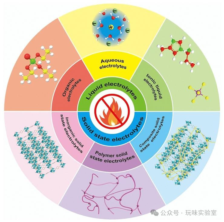
Figure 1 Classification System of Non-flammable Electrolytes for High-safety Sodium-ion Batteries
This figure illustrates the classification system of non-flammable electrolytes used in high-safety sodium-ion batteries (SIBs). Non-flammable electrolytes are primarily divided into two categories: liquid electrolytes (LEs) and solid electrolytes (SSEs). Among them, liquid electrolytes are further subdivided into organic non-flammable electrolytes, aqueous electrolytes, and ionic liquid electrolytes: organic non-flammable electrolytes require the addition of components containing elements such as fluorine and phosphorus or increasing the concentration of sodium salts to achieve flame retardancy; aqueous electrolytes are inherently non-flammable due to their water content; ionic liquid electrolytes achieve non-flammability through strong Coulombic interactions between ions. Solid electrolytes include inorganic solid electrolytes (ISSEs), polymer solid electrolytes (PSSEs), and composite solid electrolytes (CSSEs), which are composed of non-flammable inorganic materials and polymers, exhibiting high thermal stability. However, some gel-like polymer solid electrolytes may increase flammability risk due to the addition of plasticizers, necessitating strict control over the amount of plasticizer used. This classification clearly presents the structural framework of non-flammable electrolytes, providing a clear direction for subsequent targeted research and serving as a core illustration for understanding the entire non-flammable electrolyte research system.
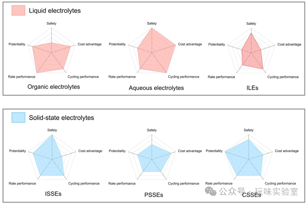
Figure 2 Performance Comparison of Different Electrolytes
This figure uses a multi-dimensional radar chart to compare the performance of liquid electrolytes (organic electrolytes, aqueous electrolytes, ionic liquid electrolytes) and solid electrolytes (inorganic solid electrolytes, polymer solid electrolytes, composite solid electrolytes) across key indicators such as safety, development potential, cost advantages, rate performance, and cycling performance. Organic electrolytes, while mature in development, exhibit poor safety; aqueous electrolytes have significant cost advantages and high safety, but their development potential is limited by a narrow electrochemical window; ionic liquid electrolytes are safe but costly, with rate performance needing improvement. Among solid electrolytes, inorganic solid electrolytes stand out in safety and development potential but are costly, and interface compatibility affects cycling performance; polymer solid electrolytes have good flexibility and moderate cost but low room temperature ionic conductivity; composite solid electrolytes combine the advantages of the former two, exhibiting balanced performance in safety and cycling performance, though cost and rate performance still need optimization. For instance, inorganic solid electrolytes like NASICON can achieve a room temperature ionic conductivity of 6.0 mS/cm and are rated highly for safety, but their cost is 3-5 times that of organic electrolytes; aqueous electrolytes cost only 1/10 of ionic liquid electrolytes, with safety ratings comparable to ionic liquids, but their rate performance is only about 60% of that of organic electrolytes. This figure intuitively reveals the strengths and weaknesses of various electrolytes, providing data support for selecting suitable electrolytes and targeted optimizations based on application scenarios.
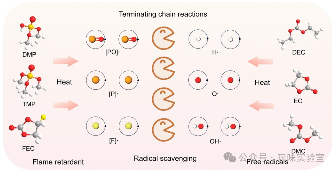
Figure 3 Schematic Diagram of Free Radical Scavenging Mechanism
This figure clearly illustrates the free radical scavenging flame-retardant mechanism of organic liquid electrolytes (LEs), which is one of the core mechanisms for achieving non-flammability. Traditional flammable organic electrolytes, when the battery heats up, evaporate solvents (e.g., dimethyl carbonate, DMC) into gas, which decompose upon encountering fire to produce H• free radicals (e.g., reaction formula RH→R•+H•); simultaneously, the cathode material, the electrolyte itself, and trace moisture decompose or reduce at high temperatures, generating O₂ and H₂. H• reacts with O₂ to produce OH• and O• (O₂+H•→OH•+O•), and these free radicals further react with H₂ (H₂+OH•→H•+H₂O; H₂+O•→OH•+H•), triggering combustion chain reactions. Non-flammable solvents (e.g., flame retardants containing phosphorus and fluorine) suppress combustion by scavenging free radicals: for example, phosphorus-based flame retardants (FRP) evaporate into gas upon heating and decompose to produce [PO]•, [P]• and other phosphorus free radicals (FRP liquid→FRP gas; FRP gas→[PO]•+[P]•), which combine with H• ([PO]•+H•→[PO]H; [P]•+H•→[P]H) to interrupt the chain reaction; fluorine-based flame retardants decompose to produce [F]•, which combines with H• and OH• ([F]•+H•→[F]H; [F]•+OH•→[F]OH), also achieving flame retardancy. For instance, adding 5wt% phosphorus flame retardant PFPN to the electrolyte can reduce the concentration of H• free radicals by over 70%, shortening the self-extinguishing time (SET) from over 30s for traditional electrolytes to 0s, intuitively demonstrating the efficiency of the free radical scavenging mechanism.
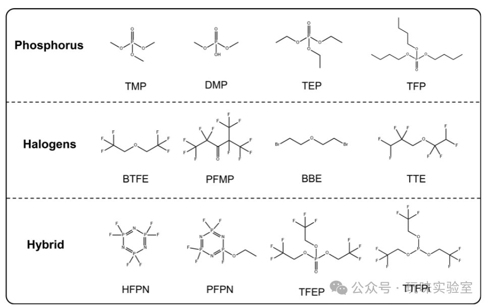
Figure 4 Molecular Structures of Typical Non-flammable Additives and Solvents
This figure presents the molecular structures of typical additives and solvents used in non-flammable electrolytes for sodium-ion batteries, which possess flame-retardant properties due to the presence of specific elements (phosphorus, fluorine, nitrogen, etc.). Among them, phosphorus-based compounds such as trimethyl phosphate (TMP) and triethyl phosphate (TEP) contain multiple P-O bonds in their molecules, which decompose easily upon heating to produce phosphorus free radicals that efficiently scavenge H• and OH• in combustion chain reactions; fluorine-based compounds such as hexafluorotriphosphazene (HFPN) and pentafluoroethoxytriphophazene (PFPN) have a high fluorine atom content in their molecules, which can not only generate [F]• free radicals but also enhance the compatibility of the electrolyte with the electrode; nitrogen-containing compounds such as phosphazene derivatives can participate in forming stable electrode-electrolyte interfaces (EEI). Each of these molecules has its characteristics: TMP has good thermal stability and low cost but poor reduction stability; HFPN has high flame-retardant efficiency (adding 5vol% can make the electrolyte self-extinguish) but has high viscosity (35 mPa·s at 25℃, higher than the 5-10 mPa·s of traditional carbonate electrolytes); TEP is low in toxicity and volatility but requires optimization for compatibility with hard carbon (HC) anodes. This figure provides structural references for designing multifunctional flame-retardant molecules, for example, by adjusting the ratio of phosphorus and fluorine in the molecules, flame-retardancy (SET≤5s) can be maintained while reducing the viscosity of the electrolyte to below 20 mPa·s, balancing ionic transport performance (ionic conductivity ≥1 mS/cm).
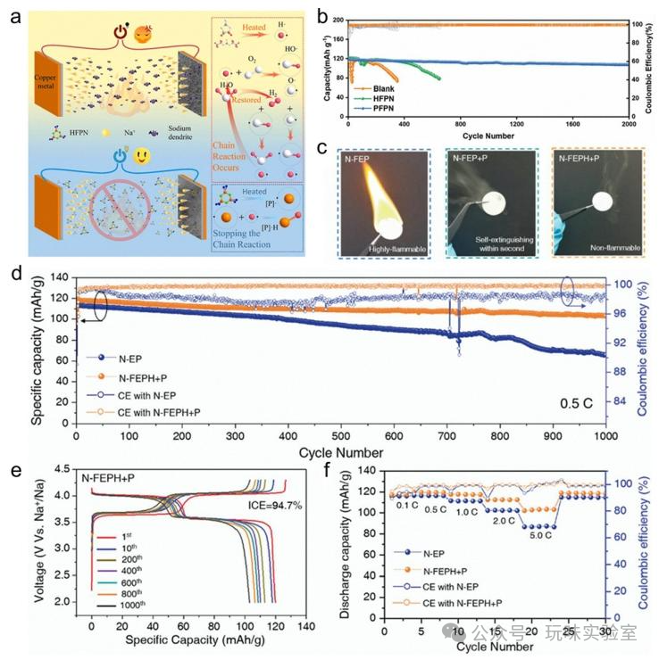
Figure 5 Effects of HFPN on Electrochemical Deposition Behavior and Performance of PFPN Electrolyte in Na||NVPOF Full Battery
This figure includes multiple sub-figures, systematically demonstrating the enhancement effects of different flame-retardant additives on the performance of sodium-ion battery electrolytes. Figure 5a shows the application of hexafluorotriphosphazene (HFPN) as an additive in commercial ester electrolytes. HFPN contains F, N, and P elements, effectively capturing free radicals, significantly suppressing the combustion of the electrolyte, while promoting the formation of a dense solid electrolyte interphase (SEI) layer containing NaF and Na₃PO₄ on the sodium anode, resulting in more uniform sodium deposition. The Na||NVP button battery cycled 800 times at 2C and 25℃, achieving a capacity retention rate of 96.49%. Figure 5b shows the electrolyte with 5wt% pentafluoroethoxytriphophazene (PFPN), which, due to its low lowest unoccupied molecular orbital (LUMO) energy level, preferentially decomposes to form a rich Na₃N and NaF SEI/cathode electrolyte interface (CEI) layer, and can also suppress HF generation through van der Waals forces. The Na||Na₃V₂(PO₄)₂O₂F (NVPOF) full battery achieved a capacity retention rate of 92.4% after 2000 cycles. Figure 5c compares flame-retardant tests, showing that the FEC/PC electrolyte (N-FEP) containing 1M NaPF₆ is flammable, but after adding 5vol% perfluoro-2-methyl-3-pentanone (PFMP) (N-FEP+P), it can self-extinguish within seconds, although PFMP has poor miscibility with traditional electrolytes and tends to separate; after adding HFE as a bridging agent (N-FEPH+P), the electrolyte achieves inherent non-flammability. Figures 5d-f show that the Na||Na₃V₂(PO₄)₂F₃ (NVPF) full battery using N-FEPH+P electrolyte exhibits excellent cycling stability (low overpotential), demonstrating good performance at various rates, for example, maintaining a capacity retention rate of over 95% after 100 cycles at a 1C rate.
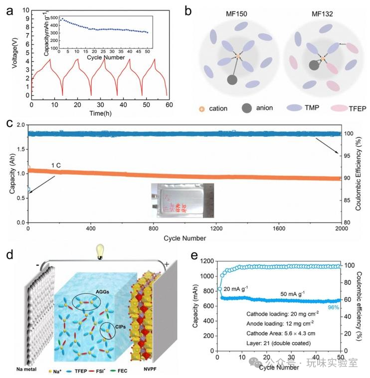
Figure 6 Charge and Discharge Curves and Cycling Performance of Sb||NaNi₀.₃₅Mn₀.₃₅Fe₀.₃O₂
This figure presents multiple sub-figures, showcasing the application and performance of non-flammable solvents in sodium-ion batteries. Figure 6a shows the Sb||NaNi₀.₃₅Mn₀.₃₅Fe₀.₃O₂ full battery using a trimethyl phosphate (TMP)-based electrolyte (0.8M NaPF₆/TMP+10vol% FEC), with FEC as an SEI-forming additive, allowing the battery to cycle stably at a current of 50mA/g, achieving capacity and cycling performance comparable to traditional carbonate electrolytes. This is the first report of a non-flammable electrolyte system for sodium-ion batteries. Figure 6b shows a full phosphorus electrolyte (NaClO₄/TMP/TFEP) containing tri(2,2,2-trifluoroethyl) phosphate (TFEP), which promotes the formation of ion-solvent coordination (ISC) structures, enhancing the interaction between cations and anions, optimizing the solvation structure and interactions. Figure 6c shows the soft-pack battery using this electrolyte with hard carbon (HC)||Na₄Fe₃(PO₄)₂P₂O₇ (NFPP), exhibiting excellent cycling performance at a current of 1A, with a capacity retention rate of 84.5% after 2000 cycles. Figure 6d shows the electrolyte based on TFEP (low concentration NaFSI/TFEP), which has good compatibility with HC anodes, allowing the HC||Na₃V₂(PO₄)₃ (NVP) full battery to cycle 300 times at 100mA/g with a capacity retention rate of 89.2%, significantly reducing exothermic reactions at high temperatures; after adding 5% FEC, the Na@Al||NVPF full battery achieves stable long-term cycling. Figure 6e shows the HC||fluorine-free Prussian blue (RPB) soft-pack battery using a 2M NaClO₄-TEP/VC electrolyte, with a cathode mass loading of about 20mg/cm², achieving an energy density of over 221.7Wh/kg based on electrode mass and 115.1Wh/kg based on battery mass, with stable cycling performance.
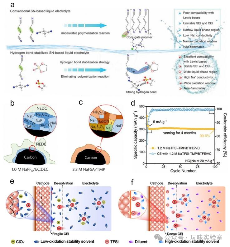
Figure 7 Design Principles of Sb||NaNi₀.₃₅Mn₀.₃₅Fe₀.₃O₂ Electrolyte and Comparison of SEI Layers
This figure includes multiple sub-figures, focusing on electrolyte structure design and interface performance optimization. Figure 7a illustrates the design principle of a butyronitrile (SN)-based electrolyte containing rich electron groups (S=O), where strong hydrogen bonds are formed between 1,3,2-dithia-2,2-dioxide (DTD) and the α-H of SN, eliminating harmful polymerization reactions of the SN-based electrolyte. DTD also participates in the sodium ion solvation layer, promoting the formation of a robust electrode-electrolyte interface (EEI) with a gradient distribution of inorganic species, allowing the HC||NVP button battery to cycle 100 times at 0.17C and 25℃, achieving a capacity retention rate of 74%. Figure 7b shows the organic-inorganic composite SEI layer formed at the HC anode with traditional dilute electrolyte (1M NaPF₆/EC:DEC), where a large amount of organic sodium ethyl carbonate (NEDC) encapsulates inorganic cores such as NaF and Na₂CO₃, with poor thermal stability of EC-derived alkyl carbonates (decomposition temperature around 80℃), affecting battery safety. Figure 7c shows the pure inorganic SEI layer formed by high-concentration electrolyte (3.3M NaFSI/TMP), composed solely of inorganic compounds like NaF, significantly enhancing thermal stability and ensuring safe and stable battery operation. Figure 7d shows the long-term cycling stability of 1.2M NaTFSI-TMP/BTFE/VC electrolyte in Na||HC batteries, cycling over 100 times at a current density of 20mA/g, achieving a capacity retention rate of 99.6%, with VC additives alleviating the hydrogen bonding between TMP and BTFE, repairing the sodium ion solvation structure. Figure 7e shows the decomposition of commercial carbonate electrolytes (e.g., DMC/EC) at high voltages, forming thick and brittle cathode electrolyte interfaces (CEI), increasing side reactions and leading to performance degradation; Figure 7f shows NaTFSI/SUL:OTE:FEC electrolyte, where OTE promotes TFSI⁻ and cyclic sulfone (SUL) to participate in the solvation layer, with SUL’s high oxidation resistance resulting in a CEI rich in inorganic S and N compounds produced by TFSI⁻ decomposition, reducing side reactions and enhancing the cycling stability of high-voltage sodium-ion batteries, for example, cycling over 200 times at 4.5V high voltage with a capacity retention rate exceeding 85%.
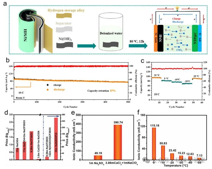
Figure 8 Preparation Scheme and Cycling Tests of Aqueous Sodium-ion Based Bivalent Mixed Batteries
This figure showcases the performance and optimization results of aqueous sodium-ion batteries (ASIBs), focusing on bivalent systems and low-temperature performance enhancement. Figure 8a presents the preparation scheme of the nano/micro-structured Ni(OH)₂ (NNH) cathode for aqueous sodium-ion based bivalent mixed batteries, with NNH as the cathode, carbon-coated NaTi₂(PO₄)₃ (NTP@C) as the anode, and 2M NaClO₄ aqueous solution as the electrolyte; during charging, Na⁺ embeds into NaTi₂(PO₄)₃ to form Na₃Ti₂(PO₄)₃, while ClO₄⁻ adsorbs onto the NNH cathode; during discharging, the process reverses. Figure 8b shows the cycling performance of this battery at room temperature and 10C rate, with a capacity retention rate of about 87% after 500 cycles, and a coulombic efficiency stable above 98%. Figure 8c illustrates the battery’s performance across a temperature range of -25℃ to 25℃, maintaining over 70% of room temperature capacity even at -20℃, demonstrating excellent wide-temperature adaptability. Figure 8d compares the costs of different aqueous electrolytes, with the cost of 3.86m CaCl₂+1M NaClO₄ electrolyte being only $0.059 per gram, significantly lower than 1M Na₂SO₄ ($0.12 per gram) and 9.2M NaOTF ($1.5 per gram), showcasing a significant cost advantage. Figure 8e compares the room temperature ionic conductivity of this electrolyte with 1M Na₂SO₄, achieving an ionic conductivity of 390.74mS/cm, which is 4.9 times that of 1M Na₂SO₄ (80mS/cm). Figure 8f shows the ionic conductivity of this electrolyte varying with temperature, maintaining 7.13mS/cm even at -50℃, far exceeding traditional aqueous electrolytes (close to 0 at -50℃), addressing the poor low-temperature performance of aqueous electrolytes and providing possibilities for energy storage applications in cold regions.
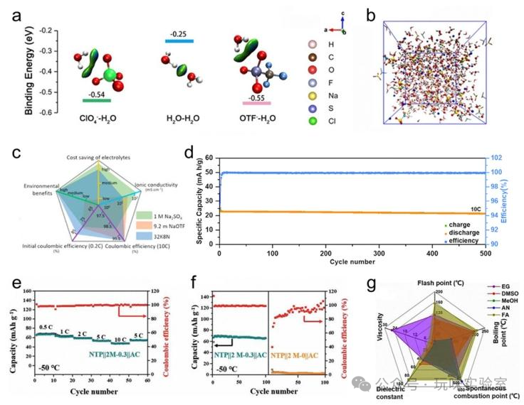
Figure 9 Intermolecular Interactions and Battery Performance of NaClO₄-NaOTF-H₂O Electrolyte
This figure presents multiple sub-figures, showcasing the structural and performance optimization of high-concentration and mixed aqueous electrolytes. Figure 9a illustrates the intermolecular interactions of 19M NaClO₄-NaOTF (17M NaClO₄+2M NaOTF) aqueous electrolyte, where ClO₄⁻, OTF⁻, and H₂O are bound through hydrogen bonds, with their binding energies being: H₂O-H₂O (-0.25eV) < ClO₄⁻-H₂O (-0.54eV) < OTF⁻-H₂O (-0.55eV), with strong binding forces suppressing the aggregation of water molecules and reducing free water. Figure 9b shows classical molecular dynamics (cMD) simulations indicating that both OTF⁻ and ClO₄⁻ participate in the sodium ion solvation structure, with this electrolyte achieving an electrochemical stability window (ESW) of 2.8V, with a cathode limit potential as low as 1.6V. The NVP@C||NVP@C battery cycled 100 times at 1C and 25℃, achieving a capacity retention rate of 87.5%. Figure 9c compares the performance of 32M potassium acetate (KAc)+8m sodium acetate (NaAc) (32K8N) electrolyte with 1M Na₂SO₄ and 9.2M NaOTF, showing that 32K8N has lower costs ($0.06 per gram vs $1.5 per gram for 9.2M NaOTF), is environmentally friendly, and achieves an initial coulombic efficiency (ICE) of 95%, higher than the 88% of 9.2M NaOTF, with an ionic conductivity of 12mS/cm, although lower than 1M Na₂SO₄ (80mS/cm), it meets the operational needs of the battery. Figure 9d shows the Na₂VTi(PO₄)₃ (NVTP)/C||NVTP/C battery using 32K8N electrolyte, achieving a capacity of 23mAh/g at 10C, retaining 21mAh/g after 500 cycles. Figures 9e-f show mixed electrolytes containing dimethyl sulfoxide (DMSO) (2M NaClO₄/H₂O+0.3 mol fraction DMSO), with the NTP@C||AC battery cycling 100 times at -50℃ and 5C, achieving a capacity retention rate of over 80%, while pure 2M NaClO₄ electrolyte (2M-0) could not operate normally at this temperature. Figure 9g compares the physicochemical properties of different organic co-solvents (DMSO, formic acid (FA), etc.), with FA having a high dielectric constant (58.5), low viscosity (1.59mPa·s), and being non-flammable, making it an excellent co-solvent; the 17M NaClO₄+FA electrolyte maintains an ionic conductivity of 10mS/cm at -50℃, broadening the ESW to 2.5V, with the Polyimide||AC soft-pack battery cycling 6000 times at 4C and -50℃, achieving a capacity retention rate of 100%.
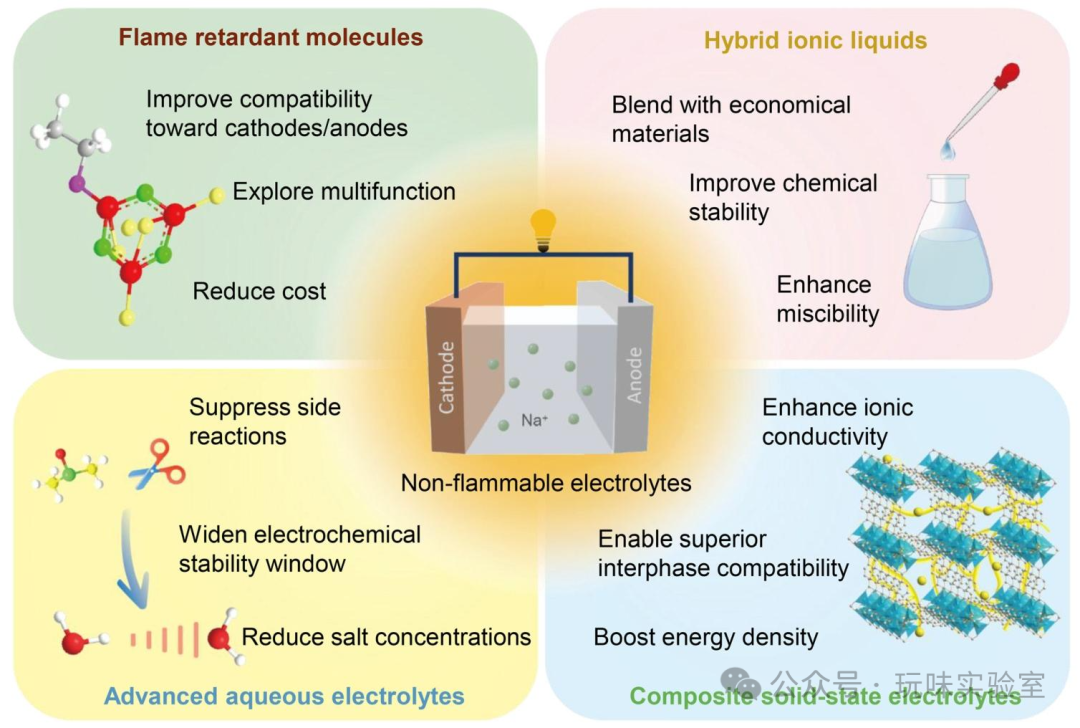
Figure 10 Battery Composition and Electrolyte Components Based on Buffered Na-Cl-IL Electrolyte
This figure illustrates the application and performance optimization of ionic liquid electrolytes (ILEs) in sodium-ion batteries. Figure 10a shows the battery composition and electrolyte components of buffered Na-Cl-IL electrolyte, composed of AlCl₃/[EMIm] Cl (molar ratio 1.5:1), 1wt% EtAlCl₂, and 4wt% [EMIm] FSI, buffered to neutrality with NaCl, capable of forming a stable SEI layer containing NaF, Al₂O₃, and NaCl at the sodium anode. Figure 10b compares the flammability of this electrolyte with traditional organic electrolytes (1M NaClO₄/EC:DEC+5wt% FEC), showing that the buffered Na-Cl-IL electrolyte-soaked separator does not ignite when exposed to fire, while the traditional electrolyte burns rapidly, proving its inherent non-flammability; the Na||NVP button battery using this electrolyte cycled 460 times at 1.3C and 25℃, achieving a capacity retention rate of 96%, with an energy density of 420Wh/kg and a power density of 1766W/kg. Figure 10c illustrates the structure of sodium metal batteries using trifluoroethoxyethane (TFEE)-assisted ionic liquid electrolyte (TILE), composed of NaTFSI salt, [Py13][FSI] ionic liquid, and TFEE (molar ratio 1:3:1), where the Na⁺ solvation layer is primarily composed of FSI⁻ and TFSI⁻, preferentially reducing to form an anion-derived SEI layer, suppressing dendrite growth. Figure 10d shows the cyclic voltammetry (CV) curves of ILE (NaTFSI/[Py13][FSI]) and TILE in Na||stainless steel (SS) batteries, with Na⁺-FSI⁻ and Na⁺-TFSI⁻ complexes preferentially reducing in TILE, resulting in a more stable SEI layer; the Na||NVP button battery using TILE cycled 2000 times at 5C and 25℃, achieving a capacity retention rate of 95.5%, addressing the issues of high viscosity (80mPa·s at 25℃) and low ionic conductivity (below 1mS/cm) of pure ionic liquid electrolytes, with TILE’s viscosity reduced to 35mPa·s and ionic conductivity increased to 3.5mS/cm.
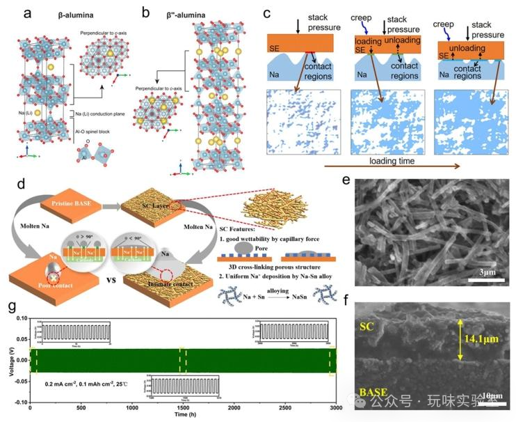
Figure 11 Crystal Structures of Na-β-Alumina and Na-β”-Alumina
This figure focuses on the structure and interface optimization of oxide electrolytes (Na-β-alumina and NASICON) in inorganic solid-state electrolytes (ISSEs). Figures 11a-b show the crystal structures of Na-β-alumina (hexagonal system, composed of Na₂O (8-11%)-Al₂O₃) and Na-β”-alumina (rhombohedral system, composed of Na₂O (5-7%)-Al₂O₃), with the β”-alumina conduction surface containing 2 Na⁺, more than the 1 Na⁺ in β-alumina, resulting in higher room temperature ionic conductivity (β”-alumina approximately 10⁻³S/cm, β-alumina approximately 10⁻⁴S/cm). Figure 11c presents a 3D time-dependent model of the interface evolution between Na-β”-alumina and sodium anode, where a stacking pressure of 15MPa ensures tighter and more uniform contact at the interface, reducing creep effects, with the battery’s coulombic efficiency improving to over 98%. However, pressures exceeding 20MPa can damage the battery structure, leading to performance degradation. Figure 11d illustrates the interface effect of carbon fiber-tin (Sn) composite (SC) layer modified on Na-β”-alumina, with a thickness of 14.1μm, where Sn optimizes contact angles with sodium through capillary forces (from 120° to 30°), forming Na-Sn intermetallic compounds that promote uniform sodium deposition. Figures 11e-f show scanning electron microscopy (SEM) images of the surface and cross-section of SC-modified Na-β”-alumina, displaying uniform coverage of the SC layer without significant defects. Figure 11g shows the long-term cycling performance of the modified Na||Na symmetric battery, cycling stably for 3000 hours at a current density of 0.2mA/cm², with the area-specific resistance decreasing from 86.5Ω·cm² to 6.6Ω·cm², significantly enhancing interface compatibility and battery stability.
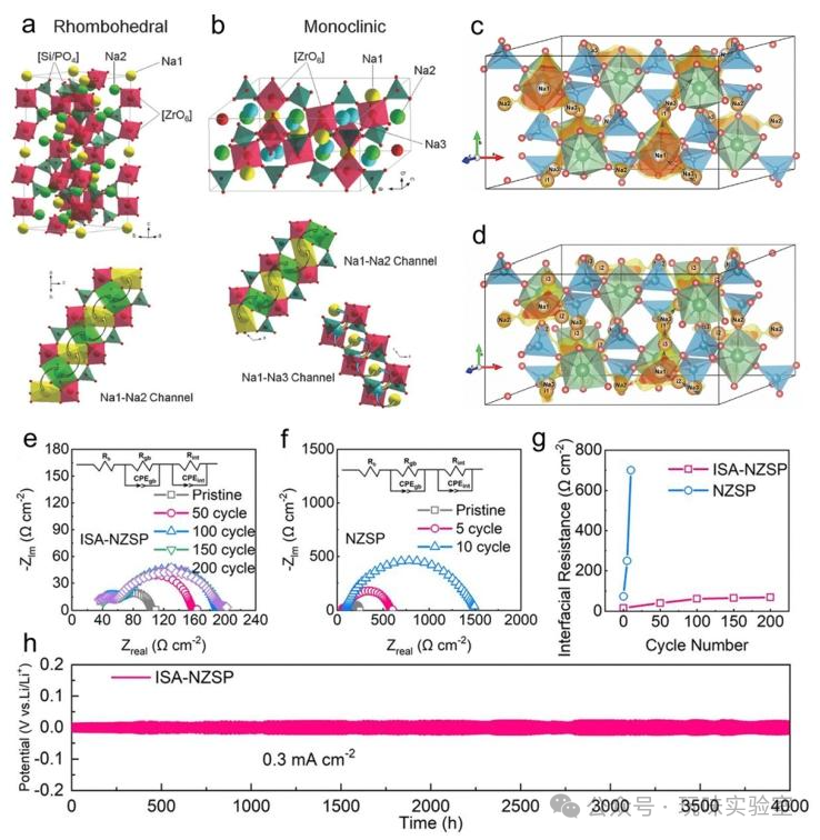
Figure 12 Crystal Structures and Ionic Diffusion Channels of Na₃Zr₂Si₂PO₁₂
This figure presents the crystal structure, ionic transport mechanism, and performance optimization of NASICON-type oxide solid-state electrolytes. Figures 12a-b show the high-temperature rhombohedral phase (R-3c space group) and low-temperature monoclinic phase (C/2c space group) crystal structures of Na₃Zr₂Si₂PO₁₂, with the rhombohedral phase containing two Na⁺ sites (Na1, Na2) and the monoclinic phase having three sites (Na2, Na3) due to the splitting of the Na2 site, forming two transport channels (Na1-Na2, Na2-Na3); the rhombohedral phase has a higher Na⁺ concentration and more vacancies, resulting in superior ionic conductivity (approximately 10⁻³S/cm at room temperature for the rhombohedral phase, approximately 10⁻⁴S/cm for the monoclinic phase). Figures 12c-d show the bond valence energy landscape (BVEL) of Na₃Zr₂Si₂PO₁₂ and Na₃.₄Zr₁.₉₅Al₀.₀₅Si₂.₃₅P₀.₆₅O₁₂, where Al doping and Si/P ratio adjustments (x=0.35, y=0.05) widen the lattice and optimize ionic transport channels, achieving a room temperature ionic conductivity of 6.0mS/cm, comparable to sulfide electrolytes. Figures 12e-f show the AC impedance (Nyquist) plots of ISA-NZSP (Na:Zr:Si:P=3.2:2:2.2:0.8) and NZSP (Na:Zr:Si:P=3:2:2:1) electrolytes, with ISA-NZSP’s bulk resistance and grain boundary resistance remaining relatively stable during cycling, indicating superior interface stability. Figure 12g compares the Na/SSE interface resistance of the two, with ISA-NZSP’s initial interface resistance at 16Ω·cm², significantly lower than NZSP’s 73Ω·cm², due to the in-situ formation of an amorphous interface phase containing Na₂ZrSi₂O₇ and Na₃PO₄, reducing interfacial energy. Figure 12h shows the long-term cycling performance of ISA-NZSP symmetric batteries at 0.3mA/cm², cycling stably for 4000 hours, with the critical current density increasing to 1.3mA/cm², highlighting the significant enhancement of NASICON electrolyte performance through structural optimization.
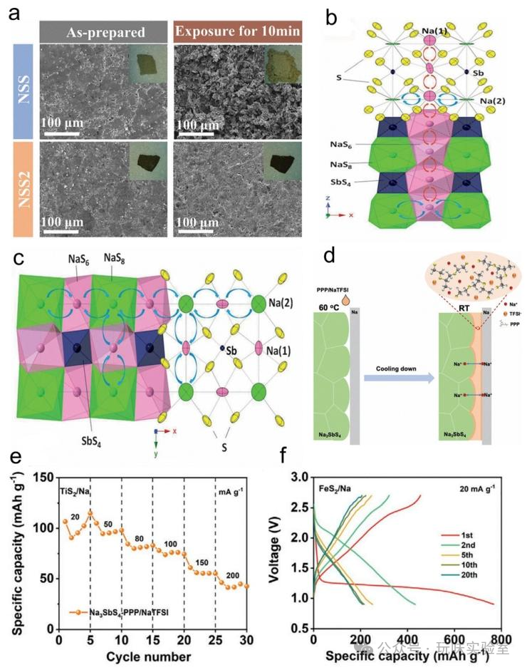
Figure 13 Cubic and Tetragonal Crystal Structures of Na₃PS₄
This figure showcases the crystal structures and phase transition characteristics of the typical Na₃PS₄ in sulfide solid-state electrolytes, which are key to understanding the ionic transport performance of sulfide electrolytes. Figure 13a shows the high-temperature cubic phase β-Na₃PS₄ (space group I-43m), with lattice parameters a=b=c=6.9965Å, containing Na⁺ sites including Na (8a), Na (16g), forming three-dimensional interconnected ionic transport channels, with a room temperature ionic conductivity of approximately 10⁻³S/cm, the highest among the three. Figure 13b shows the room temperature tetragonal phase α-Na₃PS₄ (space group P-42₁c), with lattice parameters a=b=6.9520Å, c=7.0757Å, where the Na⁺ sites are Na (12d), Na (16b), with the transport channels narrowing due to structural distortion, reducing ionic conductivity to around 10⁻⁵S/cm. Figure 13c presents the recently discovered high-temperature orthorhombic phase γ-Na₃PS₄ (space group Fddd), with lattice parameters a=6.6055Å, b=11.7143Å, c=20.7378Å, featuring a more complex structure with increased Na⁺ sites but disordered arrangement, with ionic conductivity between the cubic and tetragonal phases (approximately 10⁻⁴S/cm). Regarding phase transition temperatures, α-Na₃PS₄ transitions to β-Na₃PS₄ around 298℃, while β-Na₃PS₄ transitions to γ-Na₃PS₄ above 563℃; the cubic phase, due to its open transport channels and high Na⁺ mobility, has become a research focus in sulfide electrolytes, with doping (e.g., Sb, Sn, etc.) enabling the cubic phase to stably exist at room temperature, further enhancing ionic conductivity to above 1.0mS/cm, for example, Na₃SbS₄ achieves a room temperature ionic conductivity of 1.0mS/cm and maintains a smooth surface even after 10 minutes of exposure to air, demonstrating good air stability.
Figure 14 Comparison of NSS and NSS2 Particles Before and After Exposure to Humid Air and Crystal Planes of Na₃SbS₄ Framework Structure
This figure presents the doping modification, interface optimization, and performance enhancement results of sulfide solid-state electrolytes. Figure 14a compares the particles of Na₃-□Sb₁-4x (SnWCaTi) xS₄ (NSS, x=0; NSS2, x=0.05) before and after exposure to 50% relative humidity air for 10 minutes, showing that NSS2 maintains a smooth surface while NSS shows significant corrosion products, indicating that NSS2 possesses excellent air stability due to vacancy effects and configurational entropy coupling; the Na₅Sn||TiS₂ all-solid-state battery using NSS2 achieves a reversible capacity of 211.6mAh/g, cycling 450 times at 25℃ with a capacity retention rate of 80%. Figures 14b-c show the crystal planes of the Na₃SbS₄ framework structure along [010] and [001], with its planar channel network facilitating efficient Na⁺ transport, achieving a room temperature ionic conductivity of 1.0mS/cm; the [SbS₄]³⁻ group remains stable in air due to the strong interaction between Sb⁵⁺ (soft acid) and S²⁻ (soft base), forming Na₃SbS₄・9H₂O that remains stable. Figure 14d illustrates the schematic of adding a PPP/NaTFSI (polyethylene glycol – polypropylene glycol – polyethylene glycol block copolymer / sodium bis(trifluoromethanesulfonyl)imide) interlayer between Na₃SbS₄ and the sodium anode, enhancing interface contact and forming a continuous Na⁺ transport channel, suppressing SSE degradation. Figure 14e shows the Na||Na₃SbS₄-PPP/NaTFSI||TiS₂ battery’s rate performance at 50℃, with current density increasing from 20mA/g to 200mA/g, with less than 5% capacity loss after 20 cycles, demonstrating excellent high-rate performance. Figure 14f shows the charge and discharge curves of the Na||Na₃SbS₄-PPP/NaTFSI||FeS₂ battery at 50℃ and 20mA/g, with a specific capacity of 200mAh/g after 20 cycles, proving that the interlayer effectively addresses the interface reaction issues between sulfide electrolytes and sodium anodes.
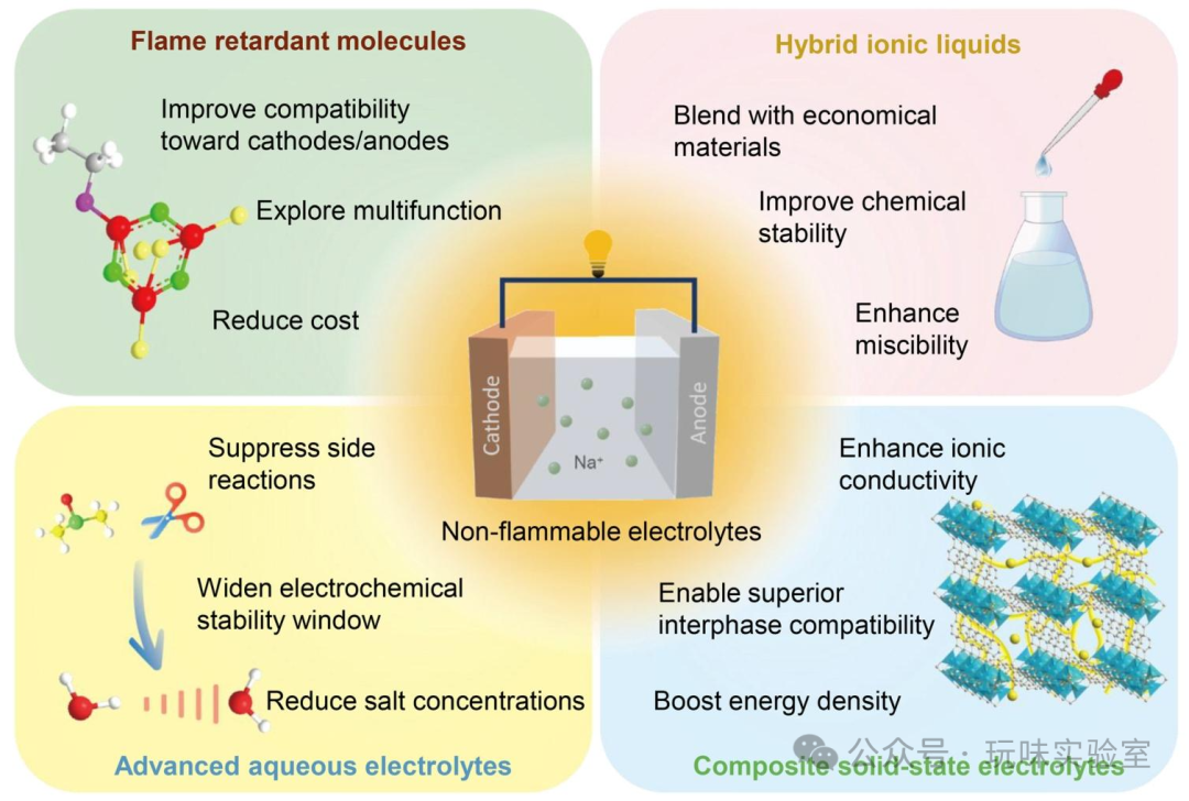
Figure 15 Amorphization of NTC Halide Electrolyte During High-energy Ball Milling and Related Performance
This figure showcases the preparation, structure, and performance of emerging inorganic solid-state electrolytes (halides, composite hydrides, and dual anion systems). Figure 15a illustrates the amorphization process of NaTaCl₆ (NTC) halide electrolyte during high-energy ball milling, utilizing NTC’s brittleness and two-dimensional characteristics, achieving an amorphous state after 40 hours of milling, with a room temperature ionic conductivity of 4.0mS/cm, far exceeding that of crystalline NTC (below 0.1mS/cm). Figure 15b shows the relationship between NTC ionic conductivity and mechanochemical reaction time, with conductivity rapidly increasing and stabilizing with extended milling time, peaking after 40 hours; the inset shows the state of NTC powder at different reaction times, transitioning from initial crystalline particles to final amorphous powder. Figure 15c presents the charge and discharge curves of NVP/NTC cathode composite materials at 0.2C (first cycle at 0.1C), achieving an initial coulombic efficiency (ICE) of 99.60%, surpassing existing lithium/sodium-ion all-solid-state batteries and liquid batteries. Figure 15d shows the long-term cycling test of this system at 60℃ and 3C, with a capacity retention rate of 81% after 4000 cycles and an average coulombic efficiency of 99.96%, demonstrating excellent high-temperature stability. Figure 15e presents the performance radar chart of Na₄B₃₆H₃₄-7Na₂B₁₂H₁₂ composite hydride electrolyte, achieving an electrochemical stability window (ESW) of 6.9V (vs Na⁺/Na), with a room temperature ionic conductivity of 1.2mS/cm, also exhibiting non-flammability, high Na⁺ transference number (0.95), and good compressibility, meeting practical needs for all-solid-state batteries. Figure 15f shows the room temperature ionic conductivity and activation energy (Eₐ) of amorphous NMOC (Na₂O₂-MCl y, M=Hf, Zr, Ta) electrolytes, with Hf-based NMOC achieving a conductivity of up to 2.0mS/cm and an Eₐ of only 0.25eV, promoting rapid Na⁺ transport due to the synergistic effect of bridging and non-bridging oxygens. Figure 15g compares the ESW of NMOC with Na₃PS₄, with NMOC’s ESW reaching 5.0V, far exceeding Na₃PS₄’s 3.5V, demonstrating superior oxidation resistance. Figure 15h shows the rate performance of NMOC-based solid-state batteries at 25℃, with a capacity retention rate of 90% at 1C and 75% at 5C, proving its good ionic transport capability.
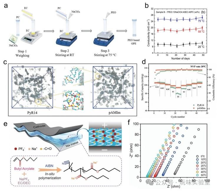
Figure 16 Na⁺ Conducting Mechanism and Related Structures in Solid Polymer Electrolytes
This figure focuses on the ionic conduction mechanism, structural design, and performance optimization of polymer solid-state electrolytes (PSSEs). Figure 16a illustrates the Na⁺ conduction mechanism in solid polymer electrolytes, where Na⁺ continuously coordinates and de-coordinates with polar groups in the polymer (e.g., -O-, -N-), achieving diffusion under the influence of electric fields, molecular thermal motion, and amorphous regions; the higher the proportion of amorphous regions in the polymer, the better the ionic conductivity (when the amorphous region accounts for 70%, the conductivity is more than 10 times that of the crystalline region). Figure 16b shows the chemical structures of EO10-PFPE (perfluoroether-end-capped poly(ethylene oxide) block copolymer), EO10-CTRL (control polymer), and NaFSI salt, with the introduction of PFPE segments enhancing the polymer’s flame-retardant and thermal stability (decomposition temperature increased from 300℃ to 350℃). Figure 16c presents the nano-structure schematic of EO10-PFPE and EO10-CTRL electrolytes, with EO10-PFPE self-assembling into an ordered nano-structure, forming continuous ionic transport channels even at high salt concentrations (EO/Na⁺=4). Figures 16d-e show the cross-sectional and surface scanning electron microscopy (SEM) images of EO10-PFPE composite solid polymer electrolytes, demonstrating complete filling of PVDF matrix pores, forming a solvent-free, flexible electrolyte membrane, with a room temperature ionic conductivity of 1.2mS/cm and Na⁺ transference number of 0.46 (at 80℃). Figure 16f illustrates the schematic of cation-template-assisted ring polymerization to synthesize star-shaped polymers containing crown ether cavities and PEO arms, where the crown ether cavity can coordinate alkali metal cations, and the PEO arms promote ionic transport, synergistically enhancing conductivity. Figure 16g shows the thermogravimetric curves of several star-shaped polymers, with most showing no significant weight loss below 300℃, meeting the thermal stability requirements for batteries (normal operating temperature <80℃); electrolytes using this polymer achieve an ionic conductivity of 0.4mS/cm at 80℃, with Na||NVP all-solid-state batteries cycling 940 times, maintaining a capacity retention rate of 97.5%.
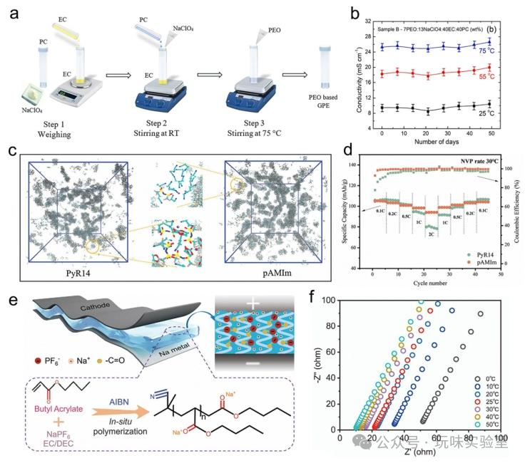
Figure 17 Synthesis Route and Related Performance of PEO-based Gel Polymer Electrolytes
This figure showcases the preparation, structure, and performance advantages of gel polymer electrolytes (an important branch of PSSEs). Figure 17a presents the synthesis route of PEO-based gel polymer electrolytes: at room temperature, NaClO₄, EC, and PC are magnetically stirred for 2-3 hours, then PEO is added and heated to 75℃ for continued stirring for 4-5 hours, forming a transparent PEO-NaClO₄-EC-PC gel electrolyte. Figure 17b shows the ionic conductivity of this gel electrolyte varying with time at different temperatures, with the optimized formulation (PEO:NaClO₄:EC:PC=7:13:40:40, mass ratio) maintaining a stable ionic conductivity of 9.5mS/cm at room temperature for 7 weeks, reaching 25mS/cm at 80℃, far exceeding that of all-solid polymer electrolytes (usually <1mS/cm). Figure 17c compares traditional ionic liquid gel electrolytes (PyR14) with plastic crystal composite gel electrolytes (pAMIm) in molecular dynamics simulation snapshots, where Na⁺ primarily coordinates with TFSI⁻ in PyR14, easily forming ionic clusters, leading to severe polarization at high currents; in pAMIm, Na⁺ preferentially coordinates with butyronitrile (SN), resulting in a more uniform ionic distribution. Figure 17d shows the rate performance of Na||NVP batteries using the two electrolytes at 30℃, with pAMIm maintaining a capacity retention rate of 85% at 10C, while PyR14 only achieves 60%, highlighting the high-rate advantage of pAMIm. Figure 17e illustrates the in-situ polymerization of BA monomers into poly(butyl acrylate) (PBA) gel electrolytes in Na||NVP sodium metal batteries, simplifying the preparation process and avoiding the risk of plasticizer volatilization. Figure 17f shows the AC impedance (Nyquist) plot of PBA-based gel electrolytes at 0-50℃, with ionic conductivity increasing with temperature, achieving 1.6mS/cm at 25℃, 3.4mS/cm at 50℃, and still reaching 0.6mS/cm at 0℃; soft-pack batteries using this electrolyte cycle 50 times at 1C, stabilizing around 92mAh/g.
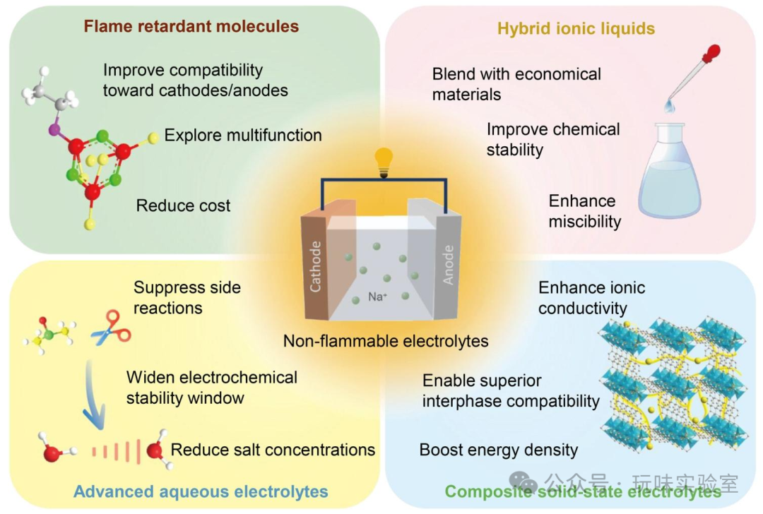
Figure 18 Surface and Cross-section SEM Images and Related Performance of PEOA-PFPE/Ca-CeO₂-3 Solid Nano-composite Electrolytes
This figure presents the structural design, interface optimization, and performance enhancement of composite solid-state electrolytes (CSSEs), which combine the advantages of inorganic and polymer electrolytes. Figures 18a-b show the surface and cross-section SEM images of PEOA-PFPE/Ca-CeO₂-3 (poly(ethylene oxide) methyl ether acrylate – perfluoroether copolymer + 3wt% calcium-doped cerium oxide nanotubes) solid nano-composite electrolytes, with Ca-CeO₂ nanotubes evenly dispersed without significant agglomeration, forming a continuous ionic transport network. This composite electrolyte achieves a room temperature ionic conductivity of 2.5mS/cm, which is 3.1 times that of pure PEOA-PFPE electrolyte (0.8mS/cm); the Na||NVP@C all-solid-state battery cycles 300 times at 1C, achieving a capacity retention rate of 84.3%, far exceeding that of pure polymer electrolyte systems (70% capacity retention after 50 cycles). Figure 18d illustrates the preparation process of composite quasi-solid electrolytes: the Na₃Zr₂Si₂PO₁₂ (NASICON) and PVDF-HFP (poly(vinylidene fluoride)-hexafluoropropylene copolymer) are electrospun to prepare composite membranes, which are then immersed in liquid electrolyte to form gel composite electrolytes. Figure 18e analyzes the mechanism at the interface of NASICON/PVDF-HFP electrospun membranes, where Lewis acid sites of NASICON adsorb PF₆⁻, promoting sodium salt dissociation, increasing free Na⁺ concentration, and forming efficient ionic transport channels. Figure 18f shows the Nyquist plots of different electrolytes at 25℃, with the ionic conductivity of composite gel electrolytes at 4.1mS/cm, which is 3.4 times that of pure PVDF-HFP gel electrolytes (1.2mS/cm). Figure 18g shows that the Young’s modulus of composite gel electrolytes reaches 5GPa, five times that of pure polymer gel electrolytes (1GPa), effectively suppressing sodium dendrite growth. Figure 18h shows the long-term cycling performance of Na||NVP batteries using different electrolytes at 500mA/g, with the composite gel electrolyte system cycling 2100 times, achieving a capacity retention rate of 83.8%, while the pure liquid electrolyte system only retains 50% capacity after 500 cycles.
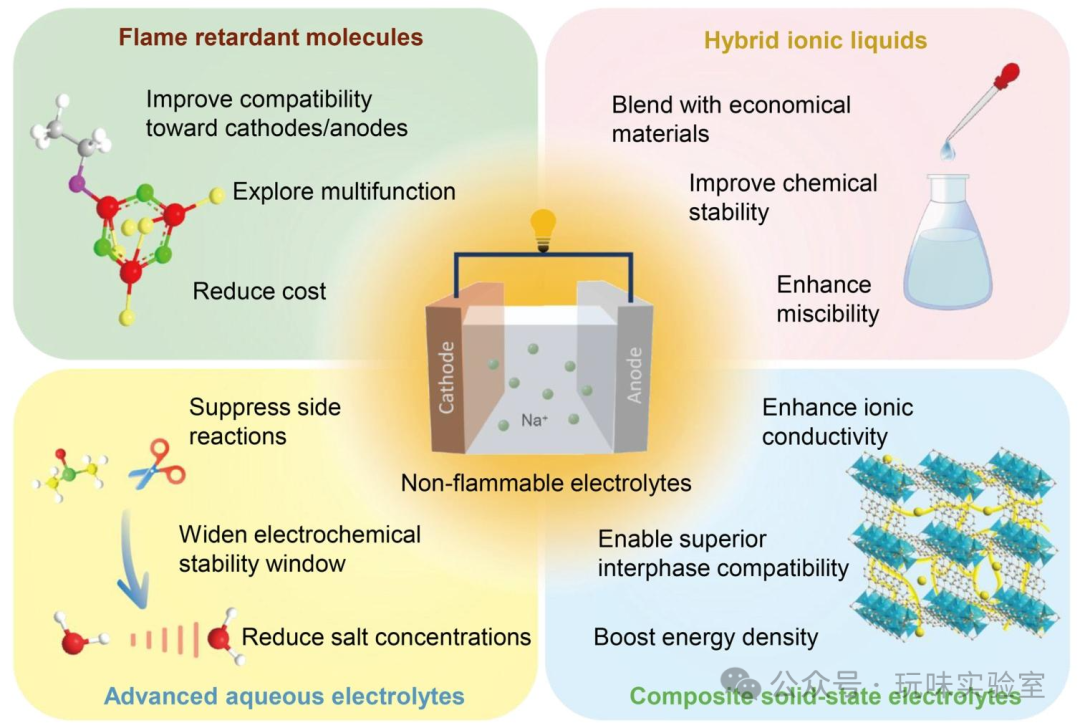
Figure 19 Research and Development Directions of Non-flammable Electrolytes for Sodium-ion Batteries
This figure systematically outlines the five major research and development directions for non-flammable electrolytes for sodium-ion batteries, providing clear guidance for the field’s development. First, developing low-cost multifunctional flame retardants: existing flame retardants (e.g., TMP, TEP) struggle to balance flame retardancy and electrochemical performance at low additive levels (<10wt%), necessitating the design of multifunctional molecules that can achieve flame suppression (self-extinguishing time ≤5s) and enhance cycling performance (capacity retention rate ≥90% after 2000 cycles) at below 5wt% addition, for example, by adjusting the phosphorus and fluorine ratios to simultaneously promote SEI layer formation. Second, developing low-concentration advanced aqueous electrolytes: high-concentration “salt-in-water” electrolytes (>10M) broaden the ESW to 2.8V but are costly and have high viscosity (>50mPa·s), requiring the introduction of new secondary salts or functional organic polar solvents to broaden the ESW to above 2.5V at 1-3M salt concentrations while reducing viscosity (<20mPa·s) to meet low-temperature (-20℃) operational needs. Third, combining ionic liquids with low-cost materials: pure ionic liquid electrolytes cost over $100 per liter, but combining them with organic solvents (e.g., TFEE) or solid electrolytes (e.g., NASICON) can maintain non-flammability while reducing costs to below $50 per liter, with ionic conductivity increased to above 3mS/cm. Fourth, optimizing the components and design of composite solid-state electrolytes: reasonably adjusting the proportions of inorganic fillers (e.g., Ca-CeO₂ nanotubes, around 5wt%), polymers (e.g., PEO derivatives), and plasticizers to avoid flammability risks (plasticizers <10wt%), achieving room temperature ionic conductivity above 2mS/cm and interfacial resistance below 20Ω·cm². Fifth, conducting overall safety research on battery systems: in addition to electrolytes, enhancing battery safety through electrode material modifications (e.g., surface coatings to improve thermal stability, increasing decomposition temperatures from 200℃ to 300℃), high-temperature resistant separators (e.g., aramid separators, with temperature resistance >200℃), and AI safety warning systems to achieve fire and explosion prevention under abuse conditions such as overcharging and compression.
4. Conclusion and Outlook
Sodium-ion batteries (SIBs) have broad application prospects in the energy storage field due to their abundant resources and low costs, but safety issues arising from traditional flammable liquid electrolytes (LEs) constrain their large-scale application, making the development of non-flammable electrolytes a key breakthrough direction. This article systematically reviews the research progress of non-flammable electrolytes for SIBs, first elucidating the flame-retardant mechanisms: inherently safe electrolytes (e.g., aqueous, ionic liquids, solid electrolytes) achieve safety through the inherent non-flammability of their components; organic liquid electrolytes achieve flame retardancy by scavenging free radicals such as H• and OH• in combustion chain reactions through compounds containing phosphorus, fluorine, etc., or by increasing sodium salt concentrations to reduce free solvent.
Based on physical and chemical states, non-flammable electrolytes are divided into two main categories: liquid and solid. Liquid electrolytes include organic (requiring the addition of flame retardants, using non-flammable solvents, etc.), aqueous (inherently non-flammable but facing issues such as narrow ESW), and ionic liquids (inherently non-flammable, but cost and viscosity are bottlenecks); solid electrolytes include inorganic (high ionic conductivity but poor interface compatibility), polymers (good flexibility but low room temperature conductivity), and composites (combining the advantages of the former two, needing component optimization). Currently, various electrolytes face challenges: organic liquid electrolytes may sacrifice electrochemical performance; aqueous electrolytes have narrow ESW; ionic liquids are costly; solid electrolytes have low room temperature conductivity and poor interface contact; and current safety assessments are often limited to ignition tests, lacking comprehensive mechanical, environmental, and electrical safety characterization.
Future research can focus on five major directions: first, developing low-cost multifunctional flame retardants to achieve flame retardancy and performance enhancement at low additive levels (≤10wt%); second, developing low-concentration advanced aqueous electrolytes to broaden ESW by introducing secondary salts or organic solvents; third, combining ionic liquids with low-cost materials to reduce costs and viscosity; fourth, optimizing the components of composite solid-state electrolytes to balance performance and safety; fifth, conducting overall safety research on battery systems, integrating electrode, separator modifications, and safety warning technologies to promote the development of inherently safe SIBs.
ReferencesDOI: 10.1039/d5cs00236b