Many MCU developers are puzzled by the practice of connecting a pair of ground capacitors on both sides of the MCU crystal, as these capacitors can sometimes be omitted. After consulting various books, it is found that there is little explanation provided; the most mentioned points are that ground capacitors have a stabilizing effect or are equivalent to load capacitors, without any in-depth theoretical analysis.
On the other hand, many enthusiasts directly overlook these two capacitors next to the crystal, believing that following the reference design is sufficient. However, this is the oscillation circuit of the MCU, also known as the “three-point capacitor oscillation circuit,” as shown in the figure below.
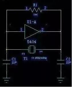
MCU Three-Point Capacitor Oscillation Circuit
In this circuit, Y1 is the crystal, equivalent to the inductor in the three-point configuration; C1 and C2 are the capacitors, while 5404 and R1 implement an NPN transistor (which can be compared to the three-point capacitor oscillation circuit in high-frequency books).
Next, we will analyze this circuit
First, in the above circuit diagram, 5404 must be paired with a resistor; otherwise, it will be in the saturation cutoff region rather than the amplification region. R1 serves as the bias for the transistor, allowing 5404 to operate in the amplification region and act as an inverter, thus fulfilling the role of an NPN transistor, which is also an inverter in a common-emitter configuration.
Next, I will explain the working principle of this three-point oscillation circuit in simple terms.
As is well known, the oscillation condition for a sine wave oscillation circuit is that the system gain must be greater than 1, which is relatively easy to achieve; however, the phase must also satisfy 360°. The issue lies in this phase: since 5404 is an inverter, it has already achieved a 180° phase shift, so it only requires C1, C2, and Y1 to achieve another 180° phase shift. Conveniently, when C1, C2, and Y1 resonate, they can achieve a 180° phase shift; the simplest way to realize this is to use ground as a reference. During resonance, since the current through C1 and C2 is the same, and ground is between C1 and C2, the voltages are opposite, thus achieving a 180° phase shift.
Furthermore, when C1 increases, the amplitude at the C2 end increases; when C2 decreases, the amplitude also increases. Sometimes, even if C1 and C2 are not soldered, oscillation can still occur, but this phenomenon is not caused by the lack of soldering C1 and C2, but rather by the parasitic capacitance of the chip pins, as the capacitance values of C1 and C2 do not need to be very large, which is very important.
So, what impact do these two capacitors have on oscillation stability?
Since the voltage feedback of 5404 relies on C2, if C2 is too large, the feedback voltage will be too low, making oscillation unstable; if C2 is too small, the feedback voltage will be too high, storing insufficient energy, making it susceptible to external interference and also radiating effects externally. The role of C1 is exactly the opposite of that of C2. When designing the board, if it is a double-sided board and relatively thick, the impact of parasitic capacitance is not significant; however, if it is a high-density multilayer board, parasitic capacitance must be considered, especially for oscillation circuits like VCOs, where parasitic capacitance should be taken into account.
Therefore, for projects used in industrial control, it is recommended not to use crystal oscillators, but rather to directly connect an active crystal oscillator.
Many times, people will use a 32.768K clock crystal for timing instead of using the MCU’s crystal frequency division for timing. The reason for this is likely not understood by many; in fact, it relates to the stability of the crystal: the higher the frequency of the crystal, the harder it is to achieve a high Q value, and the frequency stability is also poorer. In contrast, the 32.768K crystal performs well in terms of stability and other aspects, and has formed an industrial standard, making it easier to achieve high performance. Additionally, it is worth mentioning that 32.768K is half of 16-bit data, reserving the highest 1-bit carry flag, making it very convenient for internal digital calculations in timing counters.